RL78/F13, F14 CHAPTER 26 VOLTAGE DETECTOR
R01UH0368EJ0210 Rev.2.10 1574
Dec 10, 2015
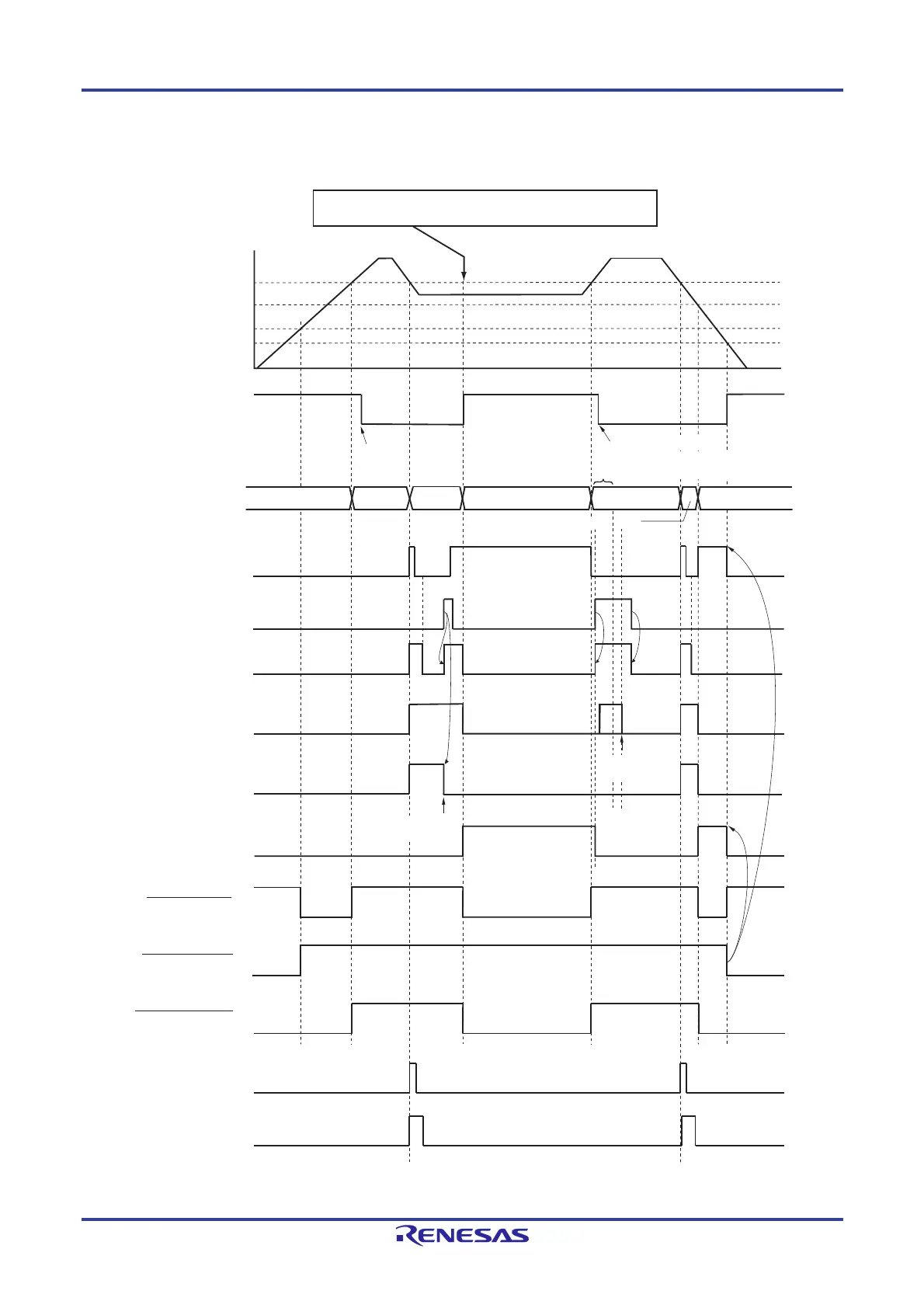
Figure 26-6. Timing of Voltage Detector Reset Signal and Interrupt Signal Generation
(Option Byte LVIMDS1, LVIMDS0 = 1, 0) (2/2)
(Notes and Remark are listed on the next page.)
INTLVI
V
POR
= 1.56 V (TYP.)
V
PDR
= 1.55 V (TYP.)
Time
H
V
LVDL
V
LVDH
Supply voltage (V
DD
)
LVIMK flag
(set by software)
Note 1
Cleared by
software
Cleared by software
RESET
Operation status
LVIF flag
LVISEN flag
(set by software)
LVIOMSK flag
LVIMD flag
LVIRF flag
LVILV flag
LVD reset signal
POR reset signal
Internal reset signal
LVIIF flag
Normal
operation
Save
processing
RESET
Normal operation
RESET
Cleared
Cleared
Note 3
Cleared by
software
Cleared by
software
Note 2
Save processing
When a condition of V
DD
is V
DD
< V
LVDH
after releasing the mask,
a reset is generated because of LVIMD = 1 (reset mode).
Wait for stabilization by software
(400 μs or 5 clocks of f
IL
)
Note 3
 Loading...


