In addition to standard control, as described in the installation and operating manual, it is possible to subordinate supplementary generator start-up
(F-L terminals on the PCB-TERMINAL BLOCK) to system inertial storage temperature, installed between the generator (PdC and supplementary
generator) and the user systems (fancoil system, radiant system, DHW).
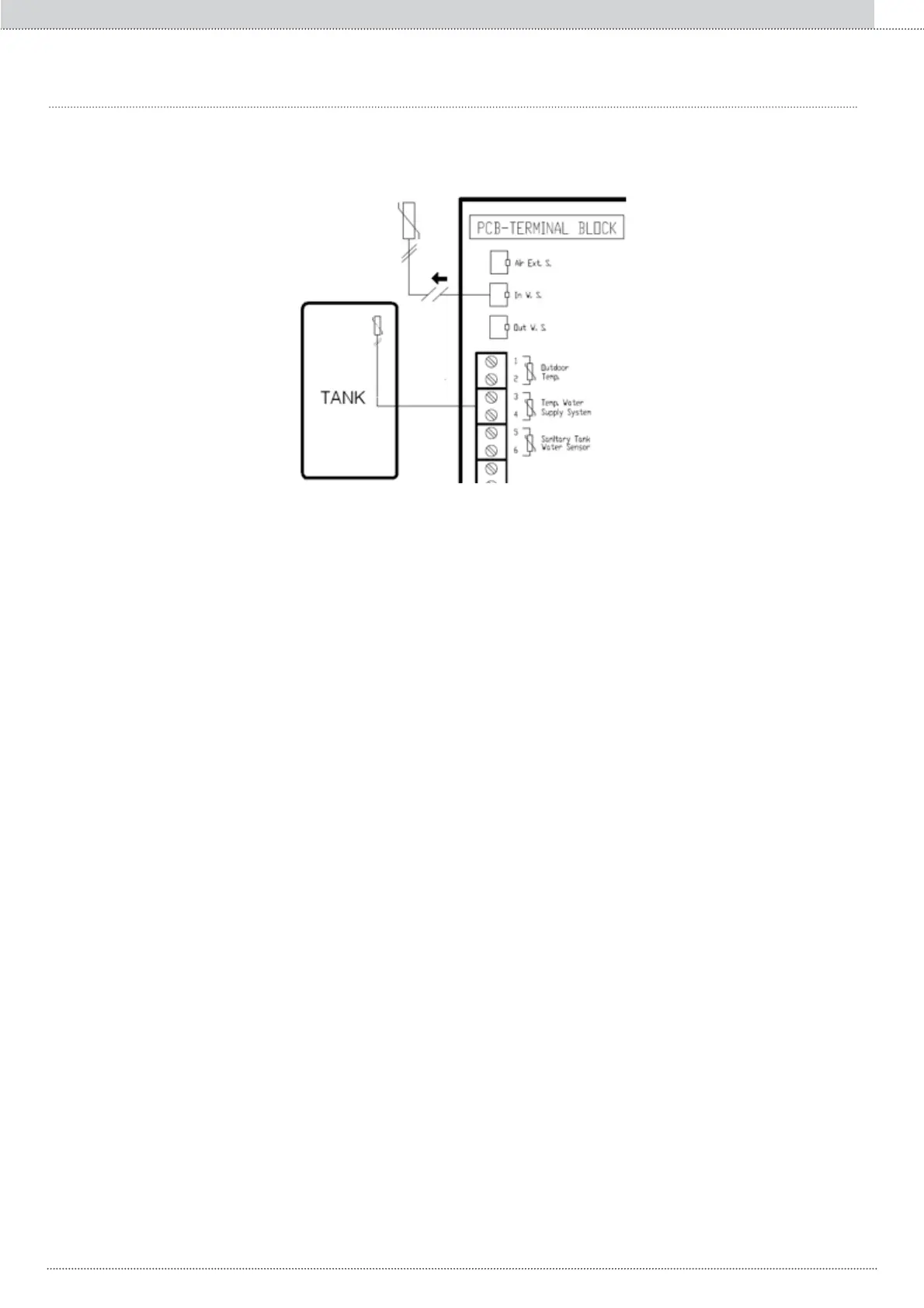
Fig. 8: Reference probe connection on the system inertial storage tank
1.10 ADVANCED SUPPLEMENTARY GENERATOR CONTROL (REFERENCE TEMPERATURE ON THE SYSTEM INERTIAL STORAGE TANK)
$WWKLVSRLQWLIWKHVXSSOHPHQWDU\JHQHUDWRULVHQDEOHGSDUWKHSUREHLQVWDOOHGRQWKHV\VWHPLQHUWLDOVWRUDJHWDQNRSHUDWHVLQSODFHRIWKH
one installed on ELECTA delivery, but only during heating function, not during DHW.
7KHIUHTXHQF\RIWKHFRPSUHVVRULVQRZPRGXODWHGVRWKDWWKHV\VWHPLQHUWLDOVWRUDJHWHPSHUDWXUHSDUIXO¿OVWKHWHPSHUDWXUHFDOFXODWHGE\WKH
FOLPDWLFFXUYH,IWKLVWHPSHUDWXUHLVIXO¿OOHGWKHFRPSUHVVRUIUHTXHQF\LV]HUR
To start the supplementary generator, THE compressor frequency needs to have a value other than zero. Accordingly, as soon as the temperature in
WKHV\VWHPLQHUWLDOVWRUDJHWDQNIXO¿OVWKHFOLPDWLFFXUYHWKHJHQHUDWRULVGLVDEOHG
NOTE:
• With DHW, standard control applies.
• System inertial storage is a tank relative to the system and must NOT be confused with the storage of domestic hot water.
7KHVWHSVUHTXLUHGWRFRQ¿JXUHDGYDQFHGVXSSOHPHQWDU\JHQHUDWRUFRQWURO
1. Disconnect connector “In. W. S.”
2. &RQQHFWDNȍWHPSHUDWXUHVHQVRUDW&EHWZHHQWHUPLQDOVRQWKH7(50,1$/%/2&.DQGVHWLWXSRQWKHV\VWHPLQHUWLDOVWRUDJHWDQN
NOTE: Maximum length of 30m.
3. Set parameter 110=2.
303
Enclosed documents EN