Back
This section explains names and functions of the parts on the back side of the RC Gate.
• Do not touch the outer screws (two outer screws shown) that are for customer engineers' operation.
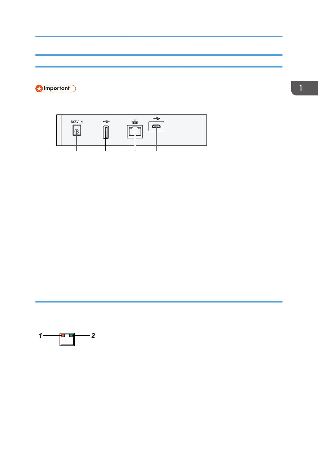
1. Power Socket
This socket is used to connect the power cord.
2. USB 2.0 interface
You cannot use this port.
3. LAN Port
The network (Ethernet) interface port to connect the RC Gate to the network. This setting remains blank as it is
not specified when this product is shipped from the factory. Specify the IP address at the initial setting.
For details, see "5. The RC Gate Initial Settings", Setup Guide.
4. USB 2.0 interface (Maintenance port)
This is a port for connecting the micro-USB cable. This port is used when a customer engineer performs
maintenance, or when the designated administrator connects a PC to perform initial settings and registration of
the RC Gate.
LAN Port Indicator
You can check the connection condition of the LAN port.
1. Orange
Indicates that the RC Gate is connected to the network.
2. Green
Indicates that the RC Gate is transmitting data.
Guide to Equipment
15