308
Installing the Expansion Board
Up to two optional Expansion Boards (ARX series; sold separately)
can be installed in the Fantom-G.
• To avoid the risk of damage to internal components that can be
caused by static electricity, please carefully observe the
following whenever you handle the board.
1
• Before you touch the board, always first grasp a metal object
(such as a water pipe), so you are sure that any static
electricity you might have been carrying has been discharged.
2
• When handling the board, grasp it only by its edges. Avoid
touching any of the electronic components or connectors.
5
• Save the bag in which the board was originally shipped, and
put the board back into it whenever you need to store or
transport it.
• Use a Phillips screwdriver that is suitable for the size of the
screw (a number 2 screwdriver). If an unsuitable screwdriver is
used, the head of the screw may be stripped.
• To remove a screw, rotate the
screwdriver counter-clockwise.
To tighten the screws, rotate the
screwdriver clockwise.
• When installing Expansion Boards, remove only the specified
screws.
• Be careful that the screws you remove do not drop into the
interior of the Fantom-G.
• Do not leave the bottom cover removed. After installation of the
Expansion Boards is complete, be sure to replace the cover.
• Be careful not to cut your hand on the opening for installing the
board.
• Do not touch any of the printed circuit pathways or connection
terminals.
912
• Never use excessive force when installing a circuit board. If it
doesn’t fit properly on the first attempt, remove the board and
try again.
913
• When circuit board installation is complete, double-check your
work.
914
• Always turn the unit off and unplug the power cord before
attempting installation of the circuit board (ARX series).
915
• Install only the specified circuit board(s) (ARX series). Remove
only the specified screws.
• When turning the unit upside-down, get
a bunch of newspapers or magazines,
and place them under the four corners
or at both ends to prevent damage to the
buttons and controls. Also, you should
try to orient the unit so no buttons or controls get damaged.
• When turning the Fantom-G8 upside-down, at least two
persons are required to safely lift and turn the Fantom-G8.
Make sure to have a firm grip, to protect yourself from injury
and the instrument from damage.
• When turning the unit upside-down, handle with care to avoid
dropping it, or allowing it to fall or tip over.
Install the Expansion Boards after removing the panel cover. Boards
can be installed in the EXP 1–EXP 2 slots.
If the slot in which an expansion board is installed differs from
the slot in which the board was installed when you saved the
live set or studio set (i.e., if you moved the expansion board to a
different slot), it will not sound the same as when you saved the
data. You must install the expansion board in the same slot it
occupied when you saved the live set or studio set.
1.
Before installing the Expansion Board, turn off the power of
the Fantom-G and all connected devices, and disconnect all
cables, including the Power cable, from the Fantom-G.
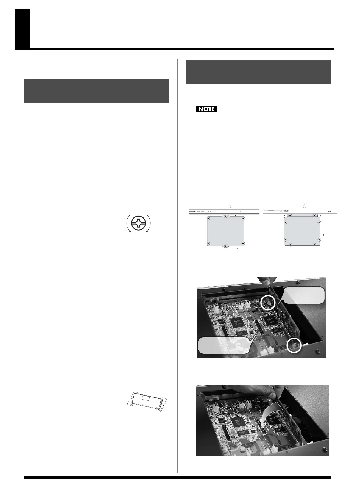
2.
From the Fantom-G, remove only the screws shown in the
following diagram, and detach the cover.
fig.30-002.e
3.
Insert the two tabs on the instrument into the holes of the
expansion board so that the connectors of the instrument
and expansion board are aligned.
* Do not touch any of the printed circuit pathways or connection terminals.
4.
Press in the expansion board in the direction shown by the
photo.
* Never use excessive force when installing a circuit board. If it doesn’t
fit properly on the first attempt, remove the board and try again.
Cautions When Installing an
Expansion Board
tightenloosen
How to Install an Expansion
Board
Screws to be removed Screws to be removed
Fantom-G6/G7 : bottom Fantom-G8 : bottom
Connector of the
instrument
Connector of the
expansion board
Fantom-G_r_e.book 308 ページ 2009年7月2日 木曜日 午後2時55分
 Loading...