Installation manual
1
R(D/B)LQ011~016AA6V3+W1
Unit for air to water heat pump system
4PW53149-1
CONTENTS Page
Introduction ....................................................................................... 1
General information................................................................................... 1
Scope of this manual ................................................................................. 2
Model identification.................................................................................... 2
Accessories....................................................................................... 2
Accessories supplied with the unit............................................................. 2
Safety considerations........................................................................ 2
Before installation.............................................................................. 3
Important information regarding the refrigerant used........................ 3
Selecting installation site................................................................... 4
Selecting a location in cold climates.......................................................... 4
Precautions on installation ................................................................ 4
Installation method for prevention of falling over........................................ 5
Installation servicing space........................................................................ 5
Typical application examples............................................................. 6
Application 1 .............................................................................................. 6
Application 2 .............................................................................................. 6
Application 3 .............................................................................................. 7
Application 4 .............................................................................................. 7
Overview of the unit .......................................................................... 8
Opening the unit ........................................................................................ 8
Main components ...................................................................................... 8
Water pipework........................................................................................ 10
Charging water ........................................................................................ 12
Piping insulation....................................................................................... 12
Field wiring .............................................................................................. 12
Installation of the digital controller ........................................................... 18
Start-up and configuration............................................................... 19
DIP switch settings overview ................................................................... 19
Room thermostat installation configuration ............................................. 19
Pump operation configuration.................................................................. 19
Domestic hot water tank installation configuration................................... 20
Initial start-up at low outdoor ambient temperatures ............................... 20
Pre-operation checks............................................................................... 20
Powering up the unit ................................................................................ 20
Setting the pump speed........................................................................... 20
Field settings............................................................................................ 21
Field settings table................................................................................... 27
Test run and final check .................................................................. 29
Automatic test run.................................................................................... 29
Test run operation (manual)..................................................................... 29
Final check............................................................................................... 29
Maintenance.................................................................................... 29
Troubleshooting............................................................................... 30
General guidelines................................................................................... 30
General symptoms................................................................................... 30
Error codes .............................................................................................. 31
Technical specifications................................................................... 33
General.................................................................................................... 33
Electrical specifications ........................................................................... 33
The English text is the original instruction. Other languages are
translations of the original instructions.
INTRODUCTION
General information
Thank you for purchasing this Rotex outdoor monoblock unit.
These units are used for both heating and cooling applications. The
units can be combined with Rotex fan coil units, floor heating
applications, low temperature radiators and domestic water heating
applications.
Heating/cooling units and heating only units
The Rotex outdoor monoblock unit range consists of two main
versions: a heating/cooling (RB) version and a heating only (RD)
version.
Both versions are delivered with an integrated backup heater for
additional heating capacity during cold outdoor temperatures. The
backup heater also serves as a backup in case of malfunctioning of
the unit and for freeze protection of the outside waterpiping during
winter time. The backup heater factory set capacity is 6 kW, however,
depending on the installation, the installer can limit the backup heater
capacity to 3 kW/2 kW. The backup heater capacity decision is a
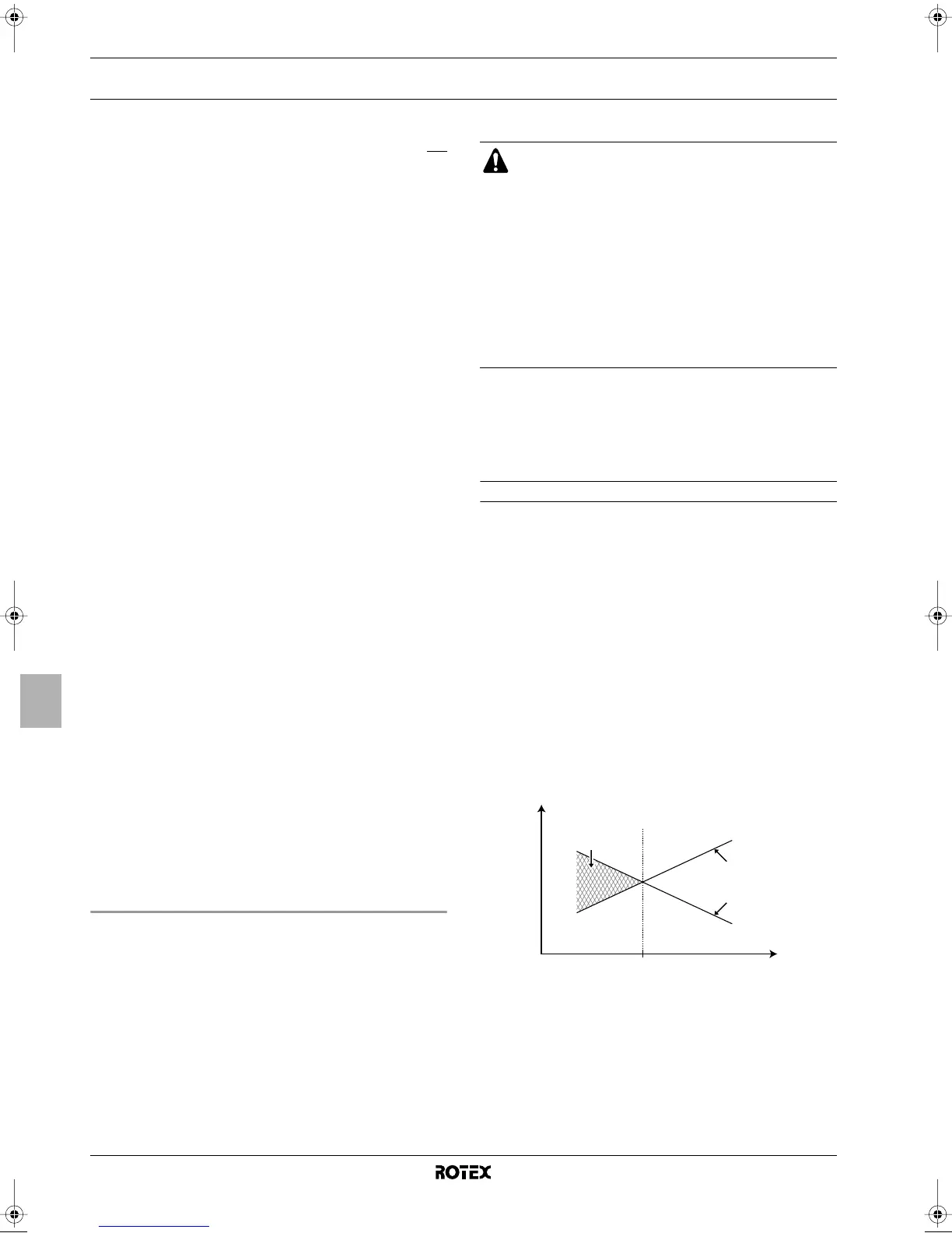
mode based on the equilibriumtemperature, see scheme below.
RDLQ011~016AA6W1 RDLQ011~016AA6V3
RBLQ011~016AA6W1 RBLQ011~016AA6V3
Unit for air to water heat pump system
Installation manual
READ THESE INSTRUCTIONS CAREFULLY BEFORE
INSTALLATION. KEEP THIS MANUAL IN A HANDY
PLACE FOR FUTURE REFERENCE.
IMPROPER INSTALLATION OR ATTACHMENT OF
EQUIPMENT OR ACCESSORIES COULD RESULT IN
ELECTRIC SHOCK, SHORT-CIRCUIT, LEAKS, FIRE OR
OTHER DAMAGE TO THE EQUIPMENT. BE SURE ONLY
TO USE ACCESSORIES MADE BY ROTEX WHICH ARE
SPECIFICALLY DESIGNED FOR USE WITH THE
EQUIPMENT AND HAVE THEM INSTALLED BY A
PROFESSIONAL.
IF UNSURE OF INSTALLATION PROCEDURES OR USE,
ALWAYS CONTACT YOUR ROTEX DEALER FOR
ADVICE AND INFORMATION.
1 Heat pump capacity
2 Required heating capacity (site dependent)
3 Additional heating capacity provided by the backup heater
4 Equilibriumtemperature (can be set through the user interface,
refer to "Field settings" on page 21)
T
A
Ambient (outdoor) temperature
P
H
Heating capacity
T
A
4
3
1
2
P
H
4PW53149-1 Page 1 Thursday, May 7, 2009 1:43 PM
 Loading...