R(D/B)LQ011~016AA6V3+W1
Unit for air to water heat pump system
4PW53149-1
Installation manual
6
TYPICAL APPLICATION EXAMPLES
The application examples given below are for illustration purposes
only.
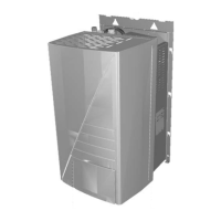
Application 1
Space heating only application with a room thermostat connected to
the unit.
Unit operation and space heating
When a room thermostat (T) is connected to the unit and when there
is a heating request from the room thermostat, the unit will start
operating to achieve the target leaving water temperature as set on
the user interface.
When the room temperature is above the thermostat set point, the
unit will stop operating.
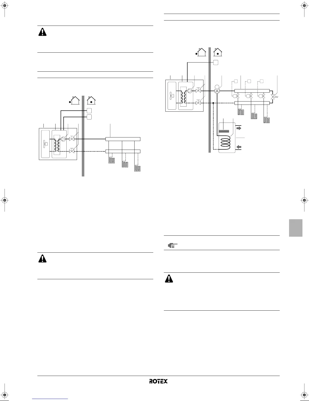
Application 2
Space heating only application without room thermostat connected to
the unit. The temperature in each room is controlled by a valve on
each water circuit. Domestic hot water is provided through the
domestic hot water tank which is connected to the unit.
Pump operation
With no thermostat connected to the unit (1), the pump (3) can be
configured to operate either as long as the unit is on, or until the
required water temperature is reached.
Space heating
The unit (1) will operate to achieve the target leaving water
temperature as set on the user interface.
When the Rotex system is used in series with another heat
source (e.g. gas boiler), it shall be made sure that the
return water temperature to the heat exchanger does not
exceed 55°C. Rotex shall not be held liable for any damage
resulting from not observing this rule.
1 Unit FHL1..3 Floor heating loop
(field supply)
2 Heat exchanger
3 Pump T Room thermostat
(field supply)
4 Shut-off valve
5 Collector (field supply) I User interface
Make sure to connect the thermostat wires to the correct
terminals (see "Connection of the thermostat cable" on
page 16) and to configure the DIP switch toggle switches
correctly (see "Room thermostat installation configuration"
on page 19).
FHL1
FHL2
FHL3
T
I
5
4321
1 Unit 9 Heat exchanger coil
2 Heat exchanger 10 Domestic hot water tank
3 Pump FHL1..3 Floor heating loop
(field supply)
4 Shut-off valve
5 Collector (field supply) T1..3 Individual room
thermostat (field supply)
6 Motorised 3-way valve
M1..3 Individual motorised
valve to control loop
FHL1 (field supply)
7 By-pass valve
(field supply)
8 Booster heater I User interface
NOTE
Details on pump configuration can be found under
"Pump operation configuration" on page 19.
When circulation in each space heating loop (FHL1..3) is
controlled by remotely controlled valves (M1..3), it is
important to provide a by-pass valve (7) to avoid the flow
switch safety device from being activated.
The by-pass valve should be selected as such that at all
time the minimum water flow as mentioned under "Water
pipework" on page 10 is guaranteed.
FHL1
FHL2
FHL3
5
43 721
M
M1
T1
M2
T2
M3
T3
10
6
98
I
4PW53149-1 Page 6 Thursday, May 7, 2009 1:43 PM
 Loading...