Installation manual
9
R(D/B)LQ011~016AA6V3+W1
Unit for air to water heat pump system
4PW53149-1
13. Manometer
The manometer allows readout of the water pressure in the
water circuit.
14. Flow switch
The flow switch checks the flow in the water circuit and protects
the heat exchanger against freezing and the pump against
damage.
15. Pump
The pump circulates the water in the water circuit.
16. Backup heater vessel
The backup heater heats the water in the backup heater vessel.
17. Backup heater thermal protector
The backup heater is equipped with a thermal protector. The
thermal protector is activated when the temperature becomes
too high.
18. Backup heater thermal fuse
The backup heater is equipped with a thermal fuse. The thermal
fuse is blown when the temperature becomes too high (higher
than the backup heater thermal protector temperature).
19. Pressure relief valve
The pressure relief valve prevents excessive water pressure in
the water circuit by opening at 3 bar and discharging some
water.
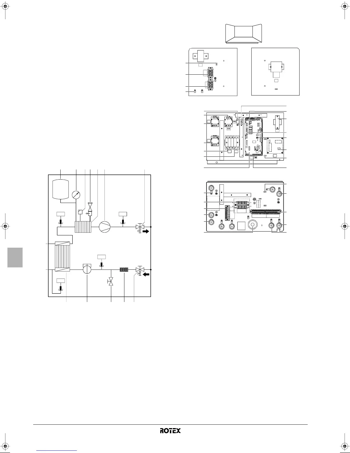
Functional diagram of hydraulic compartment (door 3)
Switch box main components (door 2)
1. Backup heater contactors K1M and K5M
2. Main PCB
The main PCB (Printed Circuit Board) controls the functioning of
the unit.
3. Booster heater contactor K3M
4. Booster heater circuit breaker F2B
The circuit breaker protects the booster heater in the
domestic
hot
water tank against overload or short circuit.
5. Backup heater circuit breaker F1B
The circuit breaker protects the backup heater electrical circuit
against overload or short circuit.
6. Ter minal blocks
The terminal blocks allow easy connection of field wiring.
7. Ter minal block for backup heater capacity limitation.
8. Cable tie mountings
The cable tie mountings allow to fix the field wiring with cable
ties to the switch box to ensure strain relief.
9. Ter minal blocks X3M, X4M
10. PCB fuse FU1
11. DIP switch SS2
The DIP switch SS2 provides 4 toggle switches to configure
certain installation parameters. See "DIP switch settings
overview" on page 19.
12. X13A socket
The X13A socket receives the K3M connector
1 Expansion vessel 8 Heat exchanger
2 Manometer 9 Flow switch
3 Air purge valve 10 Drain/fill valve
4 Pressure relief valve 11 Filter
5 Backup heater vessel
with backup heater
12 Shut-off valve water inlet with
drain valve
6 Pump R11T
R12T
R13T
R14T
Temperature sensors
7 Shut-off valve water
outlet
t
R1
t
12 6 7
1289 1011
34 5
SS2
SS1
on
off
on
K5M
K1M
F1B F2B
A11P
A4P
TR1
X10M
X2M
X5M
S1T
X4M
X3M
E5H
3
1
2
1
5
4
8
6
7
16
17
12
14
8
13
6
8
10
18
9
9
8
8
15
23
21
20
19
22
FU1
X9A
FU2
X13A
11
SS2
AC
B
D
AB
D
C
4PW53149-1 Page 9 Thursday, May 7, 2009 1:43 PM
 Loading...