RKHBRD011~016ABV1+Y1
Indoor unit for air to water heat pump system
4PW61218-1C – 2012.06
Installation manual
18
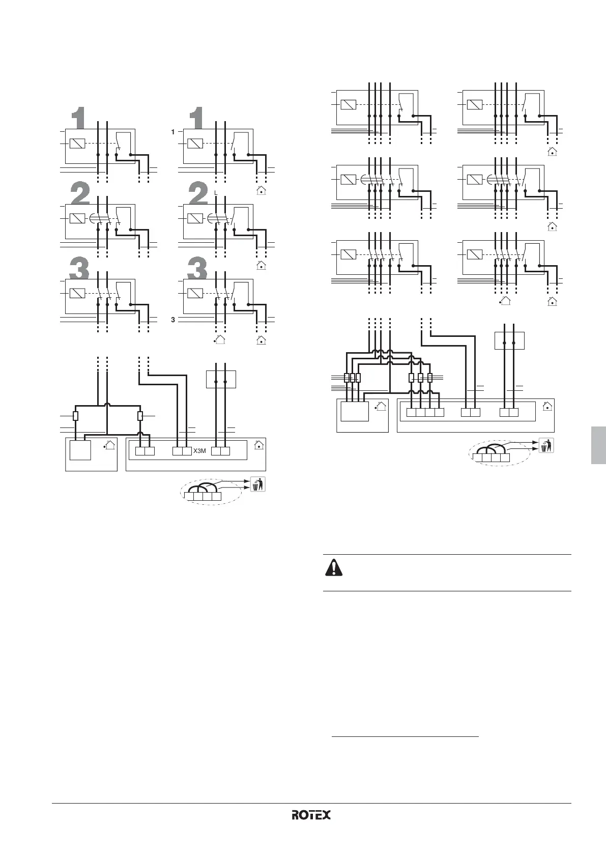
Possible types of benefit kWh rate power supply
Possible connections and requirements to connect the equipment to
such power supply are illustrated in the figures below:
For V1 unit types only (1~)
For Y1 unit types only (3~)
When the indoor and outdoor unit are connected to a benefit kWh
rate power supply, the voltage free contact of the receiver controlling
the benefit kWh rate signal of the electricity company must be
connected to clamps 7 and 8 of X3M (as illustrated in the figure
above).
When parameter [6-04]=1 at the moment that the benefit kWh rate
signal is sent by the electricity company, that contact will open and
the unit will go in forced off mode
(1)
.
When parameter [6-04]=2 at the moment that the benefit kWh rate
signal is sent by the electricity company, that contact will close and
the unit will go in forced off mode
(2)
.
1 Benefit kWh rate power supply box
2 Receiver controlling the signal of the electricity company
3 Benefit kWh rate power supply
4 Voltage free contact to indoor unit
5 Normal kWh rate power supply
6 Fuse (field supply)
1
2
3
X3M7 8 X2M8 9X1ML N
LN
2
4
1
3 5
3
LN
2
1
43
43
LN
2
1
S1S
S1S
S1S
[6-04]=1
1
2
3
LN
2
1
3
LN
2
1
43
4 4
43
L N
LN
2
1
S1S
S1S
S1S
[6-04]=2
X2M10 118 9
66
1 Benefit kWh rate power supply box
2 Receiver controlling the signal of the electricity company
3 Benefit kWh rate power supply
4 Voltage free contact to indoor unit
5 Normal kWh rate power supply
6 Fuse (field supply)
In case of benefit kWh rate power supply installation,
remove the wiring bridges on X2M before installing the
normal kWh rate power supply.
(1) When the signal is released again, the voltage free contact will close and the unit
will restart operation. It is therefore important to leave the auto restart function
enabled. Refer to field setting "[8] Option setup, [8-01]" in the chapter "Field
settings" on page 19.
(2) When the signal is released again, the voltage free contact will open and the unit
will restart operation. It is therefore important to leave the auto restart function
enabled. Refer to field setting "[8] Option setup, [8-01]" in the chapter "Field
settings" on page 19.
1
2
3
X3M7 8 X2M8 9
2
4
1
3 5
3
L1
N
2
1
L2 L3
L1
N
L2 L3
43
4
43
2
1
S1S
S1S
S1S
[6-04]=1
1
2
3
2
1
3
2
1
43
4
4
3
LN
2
1
S1S
S1S
S1S
[6-04]=2
L1 L2 X1MN X1ML3
X2M10
118 9
6
L1
N
L2 L3
L1
N
L2 L3
L1
N
L2 L3
L1
N
L2 L3
6
 Loading...