Installation manual
31
RKHBRD011~016ABV1+Y1
Indoor unit for air to water heat pump system
4PW61218-1C – 2012.06
The electrical connections on the unit should be done on the optional
demand PCB.
The configuration of pattern B is done by field settings:
1 Select the appropriate pattern: [7-02]=1
2 Turn on multiple set point 1: [7-03]=0 ➞ [7-03]=1
Turn on multiple set point 2: [7-04]=0 ➞ [7-04]=1
3 Enter the temperature multiple set point 1: [A-03] (see below)
Enter the temperature multiple set point 2: [A-04] (see below)
Configuration example:
Pattern B can also be used to do some primary multi zoning (if all set
point temperatures are selected the same, no temperature reducing
device ( ) is required).
Multiple thermo ON signals for 3 rooms can be generated. Thermo
OFF signals are only valid if all requests are OFF.
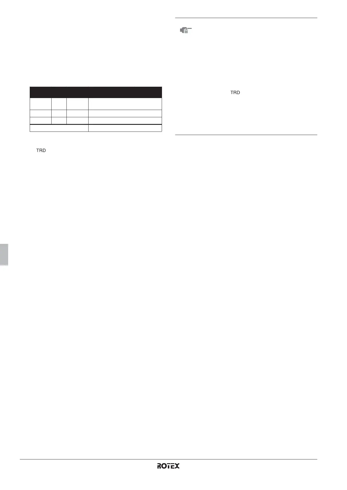
Set
point
Field
setting
Thermo status
Space 0 65°C Remote
controller
OFF ON OFF OFF OFF
Space 1 45°C [A-03] OFF ON/OFF ON ON OFF
Space 2 35°C [A-04] OFF ON/OFF OFF ON ON
Resulting heat pump water OFF 65°C 45°C 45°C 35°C
NOTE
■ Leaving water control is not allowed for pattern B.
■ It is the installers responsibility to make sure no
unwanted situations can occur (e.g. too high
water temperatures towards floor heating loops,
etc.).
■ It is the installers responsibility to make sure the
water circuit is well balanced (e.g. when a
domestic hot water request occurs, there will be
sufficient flow towards other appliances as well,
etc.)
■ Rotex does not offer any temperature reducing
device ( ). This system only provides the
possibility to use multiple set points.
■ When space 0 is in thermo OFF, but space 1 or 2
are active, space 0 will be fed with water at a
temperature equal to the highest set point of
spaces 1 and 2.
This can lead to unwanted heating of space 0.
 Loading...