Indoor Units
II-92
7
7
Console
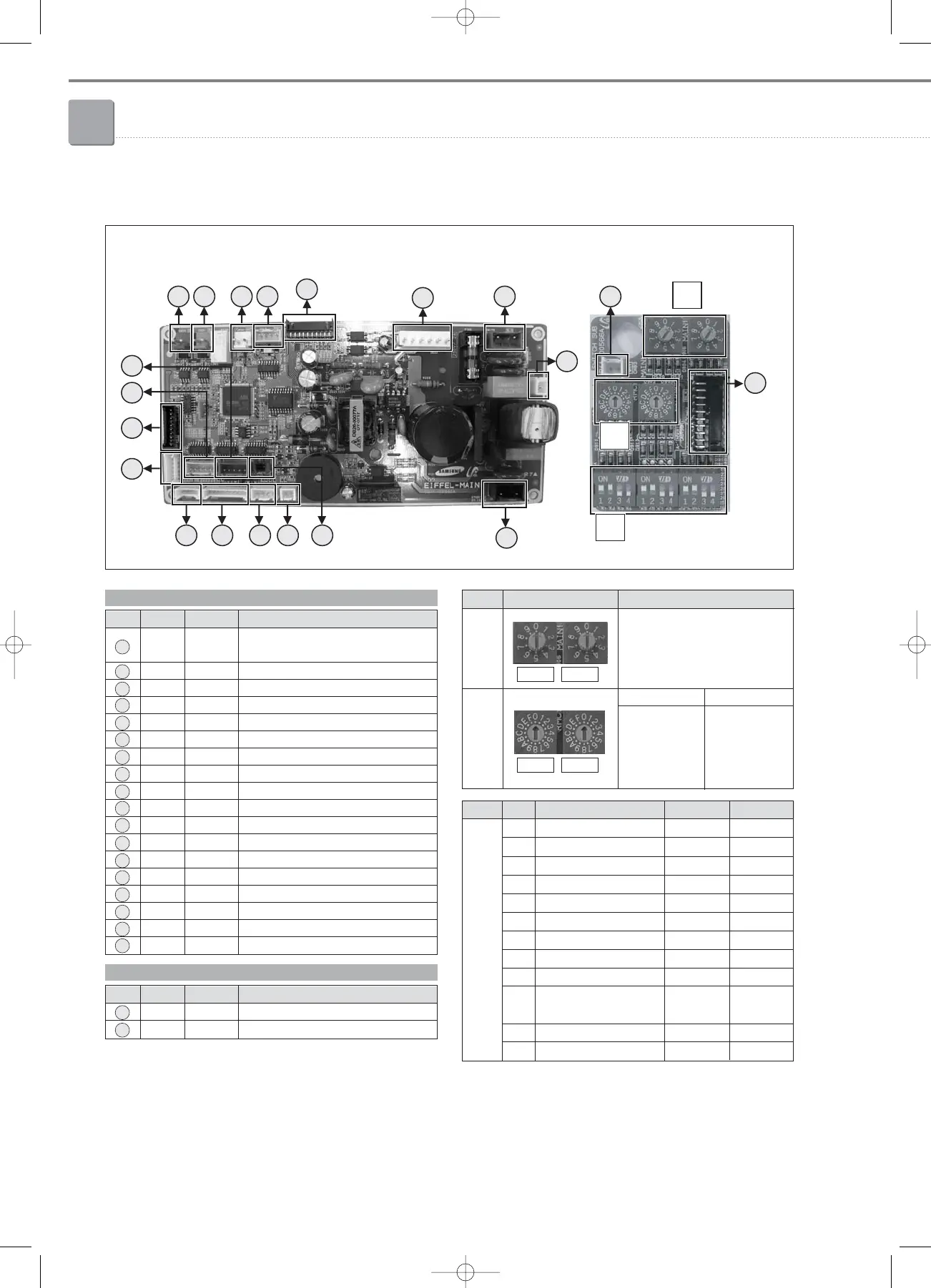
7-5. PCB connector lay-out
No. CN # COLOR FUNCTION
1 CN33 Blue
Communication with Wired Remote
Controller (COM2)
2 CN31 Red
Communication with Outdoor Units (COM1)
3 CN32 White DC12V for Wired Remote Controller
4 CN45 Yellow MPI
5 CN86 Black Main-Sub PCB connector
6 CN73 White Fan Motor
7 CN100 Blue AC 230V Input
8 CN70 White Earth
9 CN75 Black Ventilator
10 CN42 White Eva-Out Sensor
11 CN41 White Room Sensor, Eva-In Sensor
12 CN83 White Main-Display PCB connector
13 CN81 White Louver Motor
14 CN20 White MICOM Download 2
15 CN10 Black MICOM Download 1
16 CN82 Yellow Damper Motor
17 CN85 Blue EEV
18 CN87 Blue Main-Damper PCB connector
No. CN # COLOR FUNCTION
19 CN61 Black Main-Sub PCB connector
20
CN83 White External Contact Control
C
No. S/W FUNCTION ON OFF
K1 - - -
K2 Centralized Controller Not use Use
K3 RPM Up N/A N/A
K4 Optional Drain Pump N/A N/A
K5 Heating Thermo-off +2°C +5°C
K6 Filter Signal Display 1,000hrs 2,000hrs
K7 Hot Water Coil N/A N/A
K8 Electrical Heater N/A N/A
K9 Min. EEV Step at Heating Fixed 80 step 0 or 80 step
K10
Priority of Indoor unit Display
Slave
on Wired Remote Controller
(Default)
Master
K11 External Contact Control Not use Use
K12 - - -
 Loading...


