Main PCB
Main PCB Sub PCB
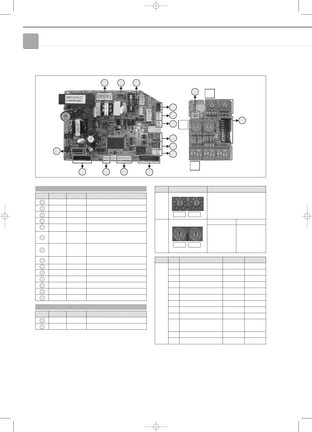
No. CN # COLOR FUNCTION
1 CN73 White Fan Motor
2 CN71 Blue AC 230V Input
3 CN44 Blue Hall IC
4 CN41 White Room Sensor, Eva-In Sensor
5 CN42 White Eva-Out Sensor
6 CN31 Red
Communication with
Outdoor Units (COM1)
7 CN33 Blue
Communication with Wired
Remote Controller (COM2)
8 CN32 White DC12V for Wired remote controller
9 CN61 Black Main-Sub PCB connector
10 CN60 White Up&Down Stepping Motor
11 CN92 White Display
12 CN93 White Display
13 CN10 Black MICOM Download
14 CN62 Blue EEV
Sub PCB
No. CN # COLOR FUNCTION
15 CN61 Black Main-Sub PCB Connector
16 CN83 White External Contact Control
C
No. S/W FUNCTION ON OFF
K1 - - -
K2 Centralized Controller Not use Use
K3 RPM Up N/A N/A
K4 Optional Drain Pump N/A N/A
K5 Heating Thermo-off +2°C +5°C
K6 Filter Signal Display 1,000hrs 2,000hrs
K7 Hot Water Coil N/A N/A
K8 Electrical Heater N/A N/A
K9 Min. EEV Step at Heating Fixed 80 step 0 or 80 step
K10
Priority of Indoor unit Display
Slave
on Wired Remote Controller
(Default)
Master
K11 External Contact Control Not use Use
K12 - - -
A
B
No.
SW01 SW02
S/W
Main Address Setting
(00~63)
FUNCTION
SW03 SW04
SW03
Address of
Interface
Module
Channel 0~2
SW04
Group Address
(RMC) for
Centralized
Control 0~F
chapter2_Indoor units(108~143) 3/14/08 22:38 Page 126
 Loading...


