Control Systems
V-42
1
1
Individual control system
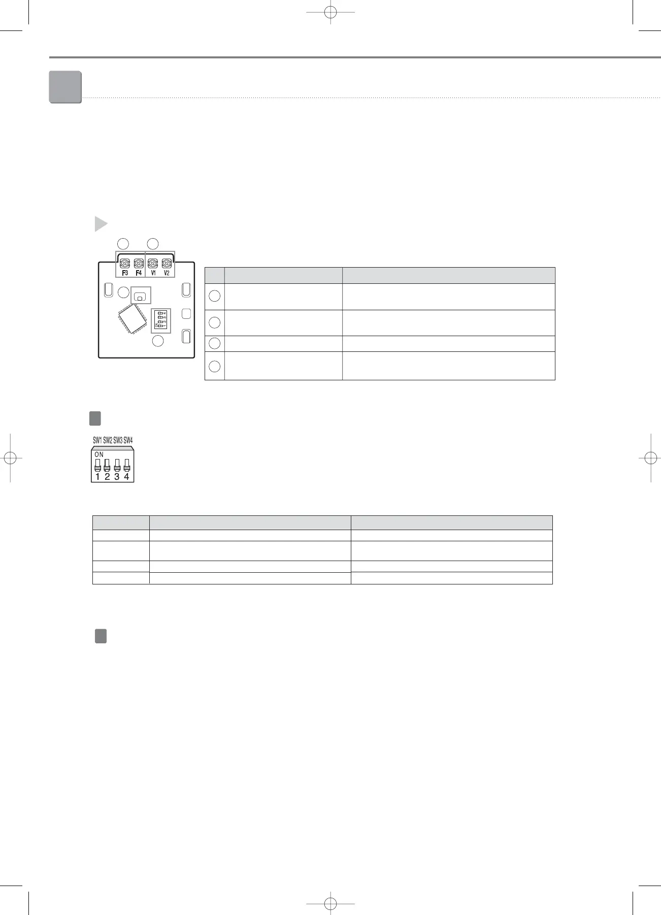
PCB description
No. Name Description
Communication wiring terminal
Connection to a wired remote controller (MWR-TH01)
(F3/F4).
Power wiring terminal (12VDC)
Connection to a wired remote controller (MWR-TH01)
(V1/V2).
Communication LED Communication with the wired remote controller
Option switches
It is possible to set additional functions for
wired remote controller.
1
2
3
4
1
3
4
4) Additional functions
1-4. 7-day scheduler (MWR-BS00)
3) Description of buttons and functions
Switch No.
SW 1
SW 2
SW 3
SW 4
OFF
-
Able to use the On/Off button in wired remote controller
connected to a 7-day scheduler
-
-
ON
-
Unable to use the On/Off button in wired remote controller
connected to a 7-day scheduler (Available for other buttons)
-
-
Able to set additional functions with the four option switches in the
7-day scheduler PCB.
❈ Default switch settings are all OFF.
Option switch
2
DS01
To use 7-day scheduler, it should be connected to the one of these products one-by-one.
Wired remote controller: MWR-TH01
Centralized controller: MCM-A202A
Required product
5) Installation
05-1_control systems(002~045) 3/15/08 4:09 Page 42