V-47
C
ONTROL
S
YSTEMS
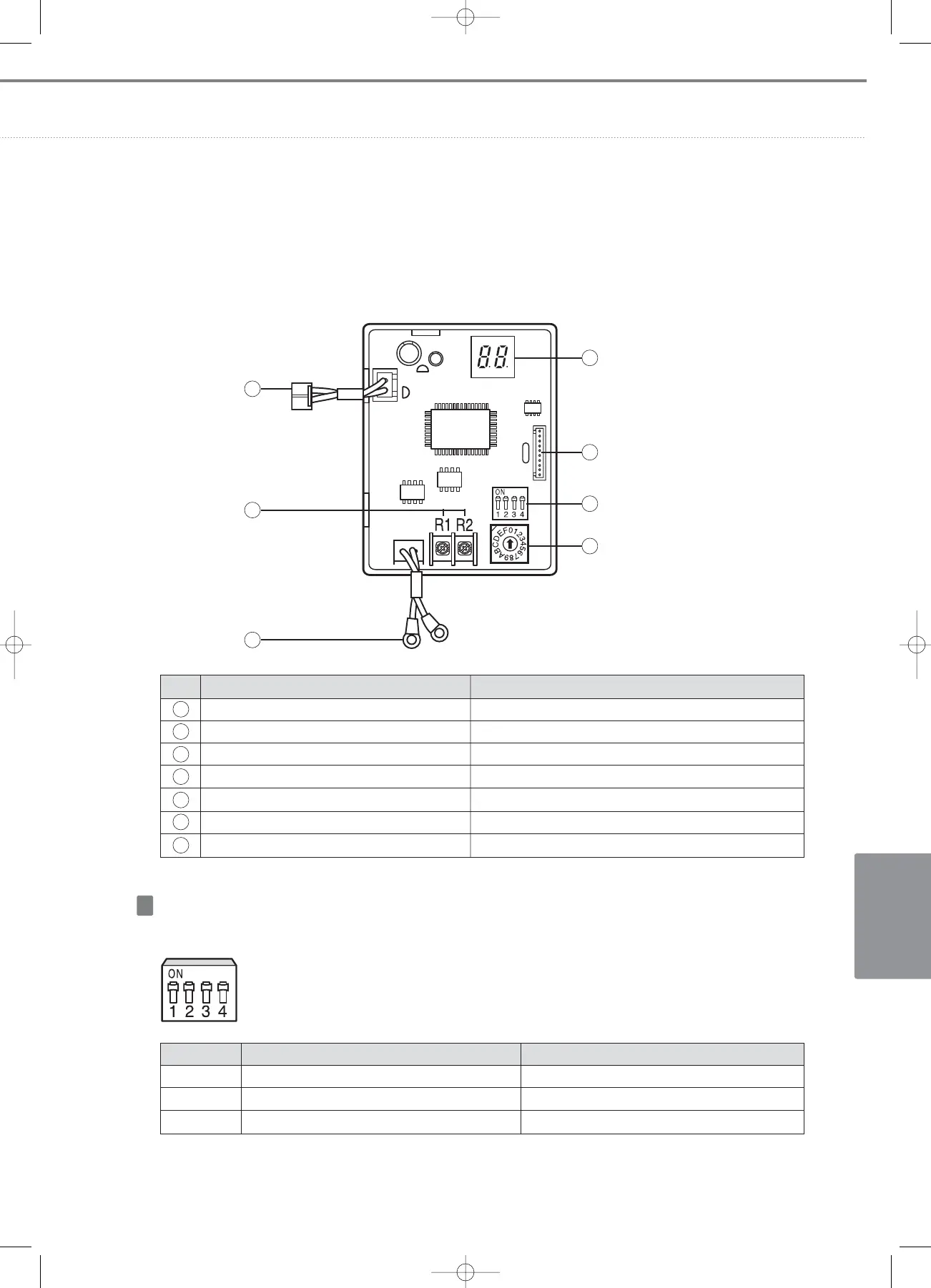
(3) Explanation of part names
No. Name Description
Communication checking 7-Segment Displays the communication state
Software update connector Using this connector, I/M software can be updated.
Option setting switches Set additional function
Address setting switch Set I/M address
Communication connector (I/M
↔
Outdoor unit) Connect to outdoor unit (Indoor unit) F1/F2
Communication connector (I/M
↔
Centralized controller) Connect to centralized controller R1/R2
Power connector DC12V power input connector (Connect to outdoor unit PCB)
1
2
3
4
5
6
7
1
2
3
4
5
6
7
Option switch
Switch No.
SW 1
SW 2
SW 3, 4
OFF
Manages indoor units with K10 to OFF
-
Set for software updating
ON
Manages indoor units with K10 to ON
-
Normal operation
• SW1 : Only for DVM PLUS outdoor unit
• SW3,4 : For software upgrade
 Loading...


