Control Systems
V-48
2
2
Centralized control system
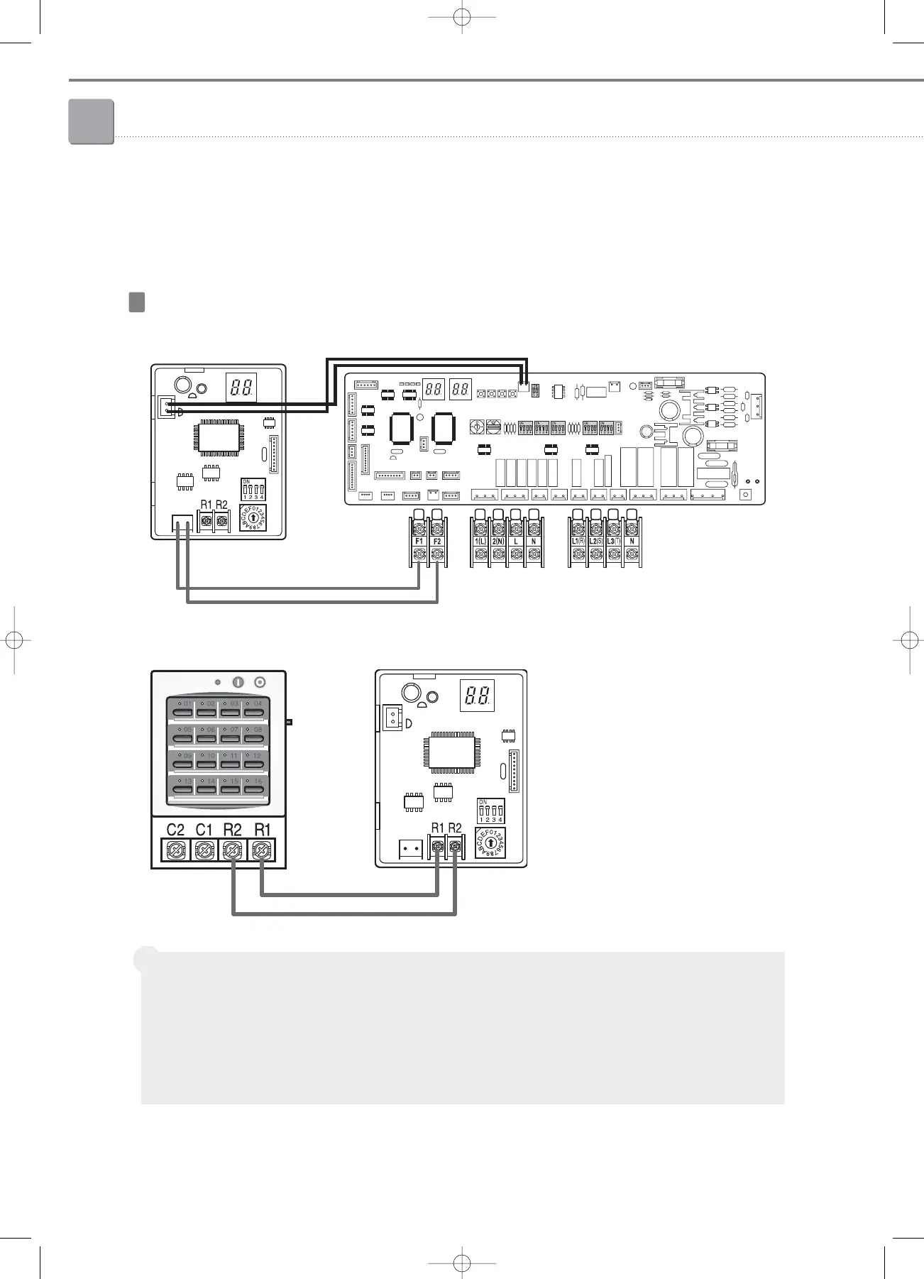
2-1. Interface module
(4) Installation
➊
Connection between interface module and outdoor unit (example : DVM PLUS)
❷
Connection between interface module and centralized controller
WIRING
Specification
• Power (V1/ V2) : DC 12V/50mA
• Communication line
- F1/F2 (Connect to Outdoor unit) : RS-485 (No-polarity), VCTF (0.75~1.5mm
2
)
- R1/R2 (Connect to Centralized controller) : RS-485 (No-polarity), VCTF (0.75~1.5mm
2
)
• 1 outdoor unit can connect only 1 interface module
(DVM PLUS outdoor unit can have 2 interface modules).
Â
 Loading...


