Control Systems
V-108
3
3
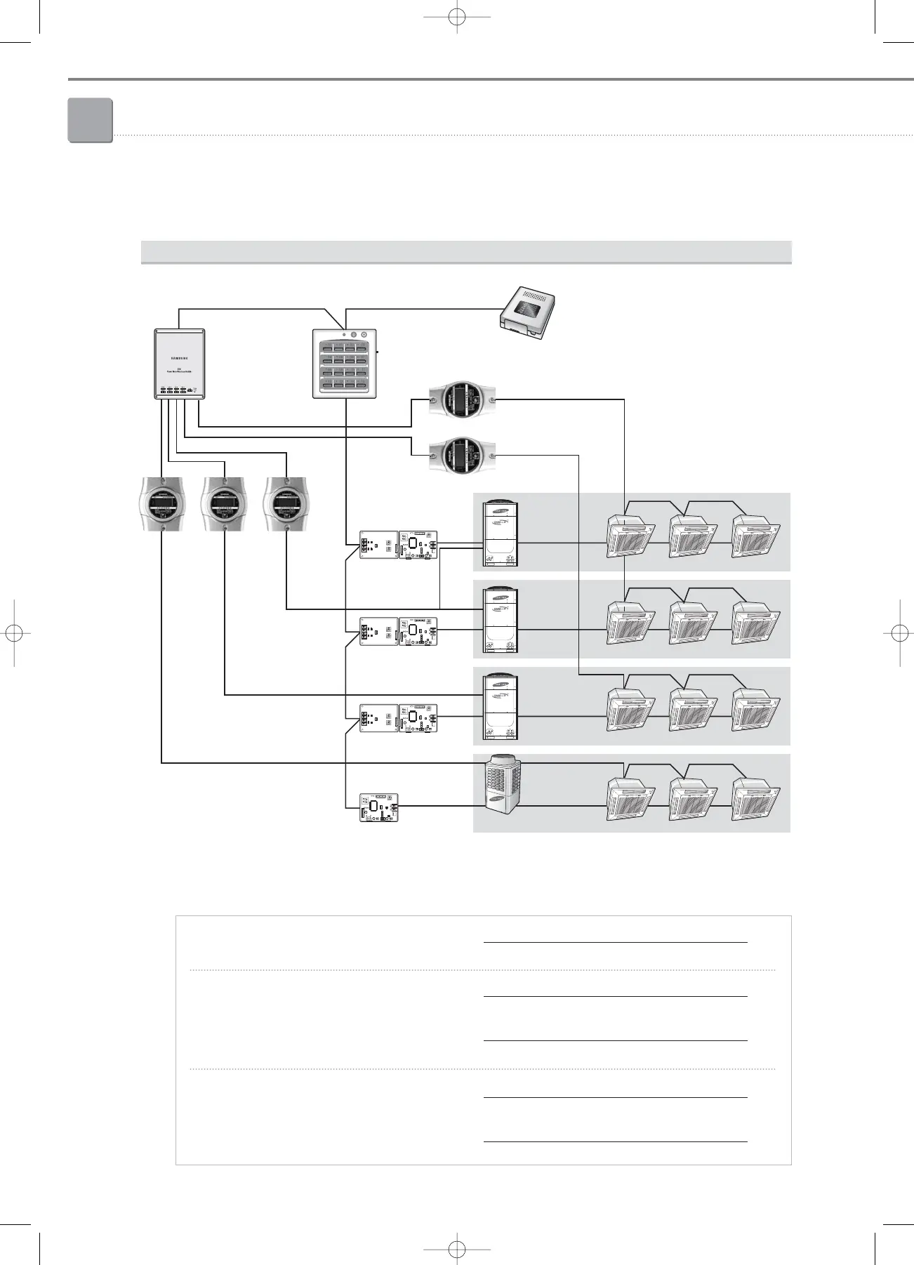
Integrated management system
Power distribution equation
E
AB C
D
G4
G3
G2
G1
SiM
DMS
Centralized
controller
C1-C2 wiring
Interface module
Power supply
Power supply
Ô When configuring the DMS and the whole system, mapping of watt-hour meters for indoor/outdoor
units must be precisely assigned for correct power distribution.
Indoor unit power X in G1 = Watt-hour A x
Main + Fan + Stand-by capacity of indoor unit X
Total capacity of G1
Indoor unit power X in G2 = Watt-hour B x
+ Watt-hour D x
Main + Fan + Stand-by capacity of indoor unit X
Total capacity of G2
Fan + Stand-by capacity of indoor unit X
Total Fan/Stand-by capacity of G2
Indoor unit power X in G3+G4 = Watt-hour C x
+ Watt-hour E x
Main + Fan + Stand-by capacity of indoor unit X
Total capacity of G3 + G4
Fan + Stand-by capacity of indoor unit X
Total Fan/Stand-by capacity of G3 + G4
3-1. DMS (Data Management Server)
05-3_control systems(082~141) 3/6/08 14:04 Page 108