Variable equipment can be connected.
Ex)Sensor, Card-key, Timer
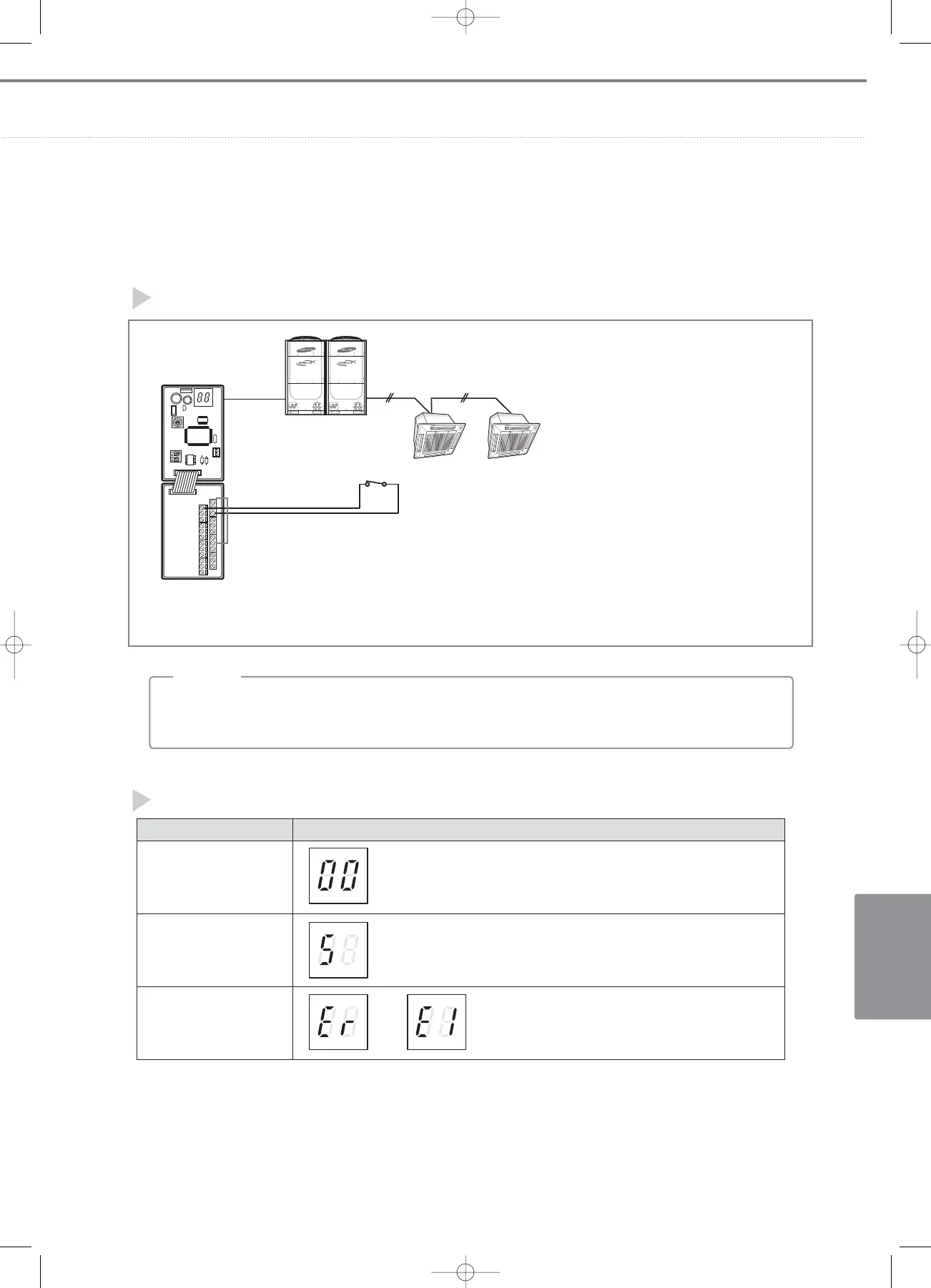
Ex) If you want to control the indoor unit of Main address “0”.
Connect the contact lines to key-tag I/M terminals labeled “0” and “GND”.
F1/F2 F1/F2
Main:0 Main:1
5) Installation
External contact line wiring
Operation display
❈ Connect the external contact input line to the connection terminal where Main address of the indoor unit to control is
written and GND terminal . (Max.16 indoor units can be controlled by the external contact input.)
• External operation input load : 5VDC/5mA
• The length of wiring between keg-tag I/M and external control equipment is 100m max.
;
NN
NN
oo
oo
tt
tt
ee
ee
Display
During tracking, display “00 ”.
Display indoor units’ Main addresses alternatively at the left segment.
ex)When I/M communicates with indoor unit of Main address “5 ”.
Display alternating Er ↔ E1.
Situation
Power input and
during tracking
Normal communication
between outdoor unit and
key-tag I/M
Outdoor unit and
key-tag I/M communication
failure
↔
05-4~6_control systems(142~171 3/6/08 14:09 Page 161