Samsung Electronics 4-33
Alignment and Adjustment
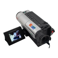
b-2. Press “ENTER(CONFIRM)” button so
that the white vector moves to the center on
screen of the vectorscope.
b-3. Store the data to mode 0A2, 0A3, 0A4 and
0A5.
b-4. The OSD shows “OK!”.
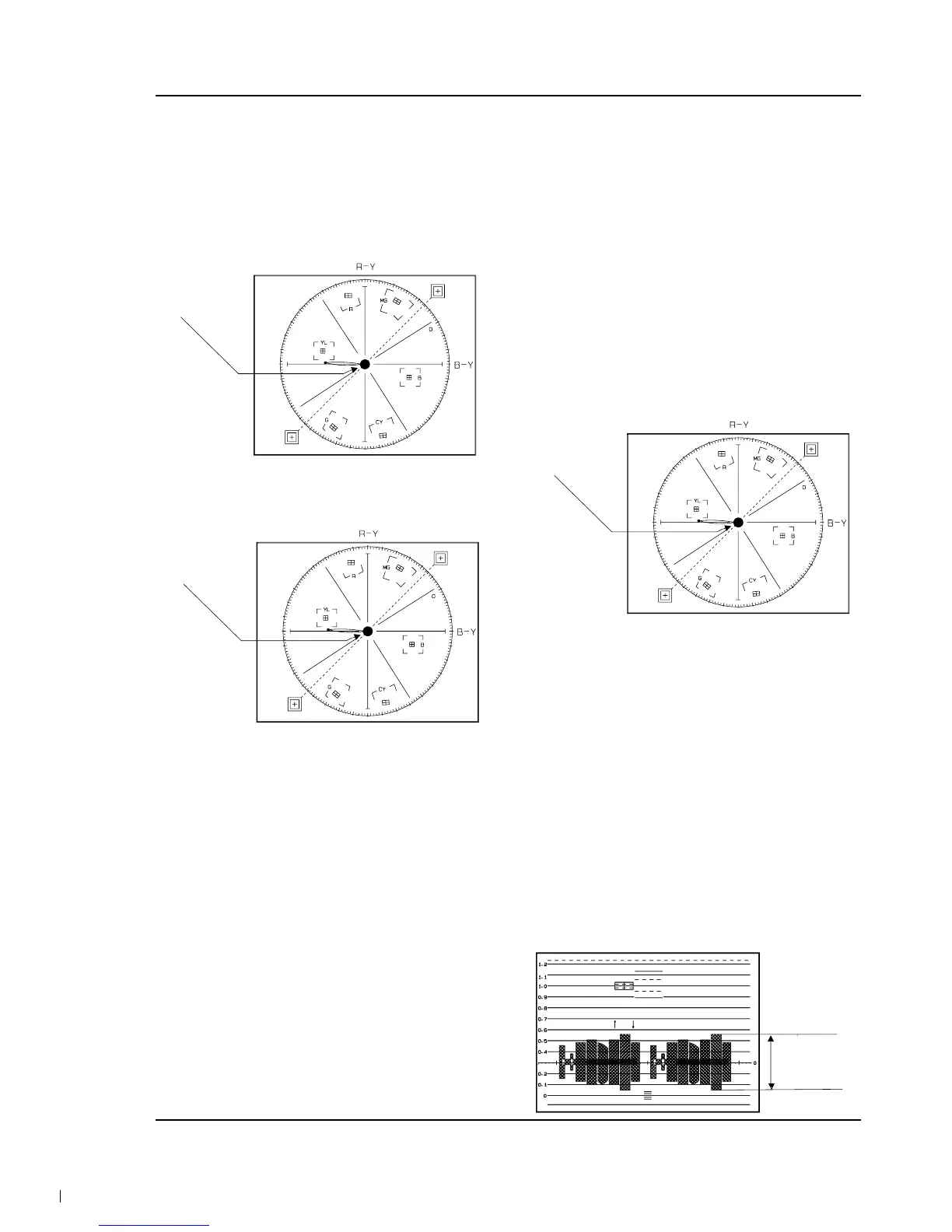
6. Pre white balance (I) ; (R-Y)
1) Camera “E-E”, 3100°K gray-scale chart.
2) Video(output) jack and AF MICOM.
3) Connect vectorscope input jack to video(out-
put) jack.
4) Press the “BLC(MODE UP)/FADE(MODE
DOWN)” button so that pass through 272, 273,
274, 275 and then the OSD state is “272. XX
XX(High)””273. XX XX(Low)”.
5) Aim the camera at a 3100°K gray-scale chart
illuminated at 1500 to 2000 lx.
6) Adjust the “ P.AE(DATA UP)/DSE(DATA
DOWN)” button so that the white vector moves
to the R-Y axial on screen of the vectorscope.
Note : Bright dot shifts after the confirm button is
pressed.
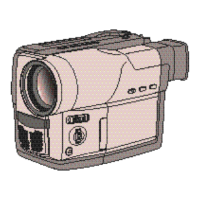
7. Pre white balance (II) ; (B-Y)
1) Camera “E-E”, 3100°K gray-scale chart.
2) Video(output) jack and AF MICOM.
4) Connect vectorscope input jack to video(out-
put) jack.
3) Press the “BLC (MODE UP)/FADE(MODE
DOWN)” button so that the OSD state is “274.
XX XX(High)””275. XX XX(Low)”.
5) Aim the camera at a 3100°K gray-scale chart
illuminated at 1500 to 2000 lx.
6) Adjust the “P.AE(DATA UP) /DSE(DATA
DOWN)” button so that the white vector moves
to the B-Y axial on screen of the vectorscope.
Note : Bright dot shifts after the confirm button is
pressed.
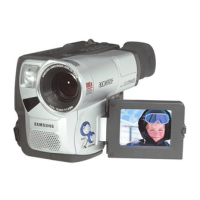
8. R-Y Gain
1) Camera “E-E”, 3100°K color bar chart.
2) Video(output) jack and register of EEPROM.
3) Connect video(output) jack to waveform moni-
tor input jack and monitor TV jack respectively.
4) Press the “BLC(MODE UP)/FADE(MODE
DOWN)” button so that the OSD state is “280.
XX XX(High)””281. XX XX(Low)”.
5) Aim the camera at a color bar chart illuminated
at 1500 to 2000 lx.
6) Adjust the “P.AE(DATA UP)/DSE(DATA
DOWN)” button so that the red level is
NTSC : 70IRE, PAL : 500mV
7) Be sure to press the “ENTER(CONFIRM)” but-
ton to memorize setting.
Note : Bright dot shifts after the confirm button is
pressed. (outdoor : 034, 035)