Samsung Electronics4-42
Alignment and Adjustment
TAPE
*NTSC
STANDARD COLOR BAR TAPE
RECORDED WITH SP SPEED
POWER SOURCE
NONE
NONE
061
HD SWP
EQUIPMENT
OTHER
TEST POINT
ADDRESS
NAME
1. Kinds of adjustment in PLAY mode.
4-3-3 Adjustment
ADDRESS NAME
NORMAL MODEL HI 8 MODEL
NTSC PAL NTSC PAL
061
062
HD SWP
Adjustment
1C
Model code setting
063
32. 768 KHZ CLOCK
064
MODEL CODE
065
D.ZOOM SIZE
TBC DEFAULT
05
88, 99 (for the VP-L750D)
2. Adjustment
* Please keep the order according to explanation.
2-1. Setting of the model code0
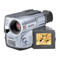
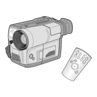
a. Preparation
b. Connect a power source.
c. Get into the VCR adjustment mode.
d. Press the “BLC(MODE UP)” or
“FADE(MODE DOWN)” button of
Camcorder so as to select the address 063.
e. Press the “DSE(DATA DOWN)/P.AE(DATA
UP)” so that OSD shows“ ”ERR:XX EVR: XX”
“XX” is different dependent on the model as
below.
f. Be sure to press the “ENTER(CONFIRM)” but-
ton on Camcorder to memorize setting.
g. Reset the power source so as to fix the new
data to the Camcorder’s EEPROM.
TAPE NONE
POWER SOURCE
NONE
NONE
063
MODEL CODE0
EQUIPMENT
OTHER
TEST POINT
ADDRESS
NAME
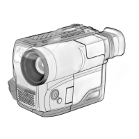
2-2. Head Switching Point
: This adjustment is performed after the
replacement of deck mechanism.
• Without this adjustment, there will be a noise
in playback picture.
a. Preparations
b. Connect a power source.
c. Get into the VCR adjustment mode.
d. Press the “BLC(MODE UP)” or “FADE(MODE
DOWN)” button of Camcorder so as to select
the address 061.
e. Insert the Standard Color Bar Tape and press
the “PLAY” button.
Note : If there is no video out, when you pressed
the “PLAY” button, you can not adjust the
Head Switching Point.
It may be caused by maladjusted VIDEO
block.
In this case, adjust the VIDEO block before
the Head Switching Point.
01
05
01
MODEL NAME ADDRESSED CODE
SCL750 85
SCL770
87
VP-L700 80
VP-L700U 8A
VP-L710 81
VP-L750
VP-L750D
VP-L770
85
86
87
NTSC
PAL
SCL710 81
SCL700 80