Samsung Electronics4-38
Alignment and Adjustment
4-2-6 EVF Adjustment
4-2-4 (a) PREPARATION
1. How to get into the EVF adjust mode.
(b) ADJUSTMENT
1. Video gain adjustment
1) Connect TP-V on PCB to PROBE.
2) Adjust VRE02 and check that A level is 2.5Vp-p. if not, adjust A level to be 2.5Vp-p.
Notes : When XX XX is shown in service adjustment procedures, this indicates variable values.
1. Connect the power source (battery/DC
cable).
2. Set the mode switch of the camcorder to
“CAMERA” position.
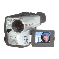
3. Disassemble EVF and use oscilloscope to
measure waveform of TP-V.
STEP1
View color bar. (If you have not color bar.,
you can view white picture)
STEP2
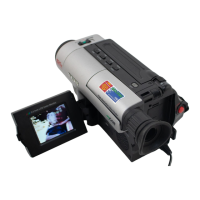
<Position of TP-V on EVF PCB>
6PIN CONNECTOR
VR
V
<TP-V Wave form>