Samsung Electronics 4-39
Alignment and Adjustment
1. Equipment :
1) Monitor TV.
2) Dual trace oscilloscope of over 20MHz band,
incorporates delay mode.
(Use 10 : 1 probe unless otherwise specified.)
3) Frequency counter
4) DC power supply.
5) Alignment tape (Colour bar : SP)
6) 8mm Video Tape for record.
2. Composition of VCR P.C.Boards
1) Main PCB (system control/servo, video, audio,
camera)
2) Rear PCB
3) Battery-Terminal PCB
4) Front PCB
3. How to get into service “ADJUST” mode.
4-3 VCR Section Adjustment
4-3-1 Preparations
1. Connect the power source (battery/DC cable).
2. Set the program selector of the camcorder to
PLAYER position.
3. Press the eject key to eject mode.
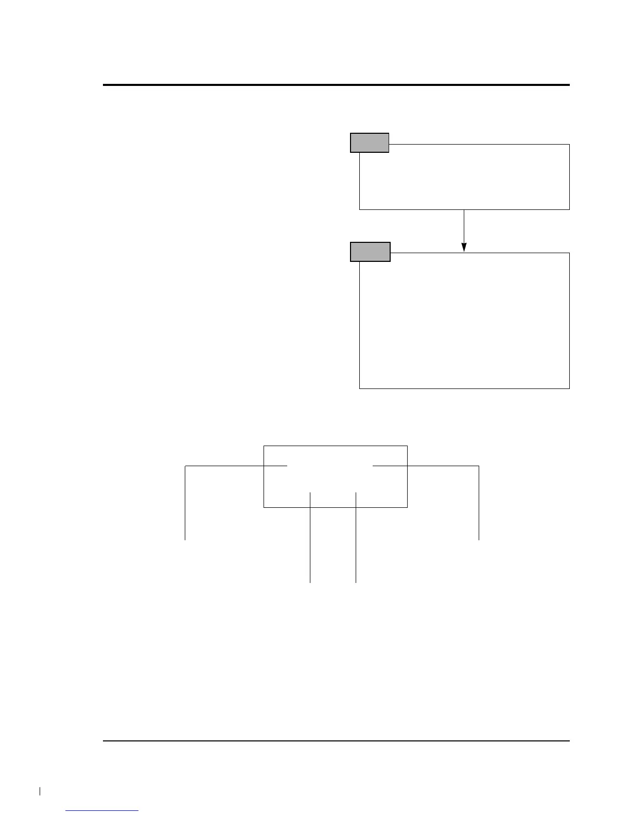
STEP 1
1. Press and hold “STOP” and “EJECT” button
on the Camcorder at the same time for more
than 5 seconds.
2. If the adjustment mode displayed like the fig-
ure below, VCR adjustment mode has been
successfully activated.
3. Insert tape into housing ass’y and then per-
form the adjustments.
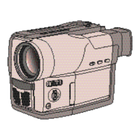
STEP 2
061.
EPR:XX EVR:XX
TV or EVF/CVF monitor
Address of the adjustment mode.
: there are 061h to 1 ch.(refer xxxx)
Name of the adjustment mode.
: every address have a name like
this (refer xxx)
Present data
: be adjusted before.
New data
: be adjusted newly.