Saia-Burgess Controls AG
Hardware manual for PCD3 series │ Document 26-789 ENG19│ 2018-06-29
Optional memory upgrades
PCD3.Mxxx0 Classic CPU and expansion enclosure
3-63
3
Operating mode switch
Behindthelabelclipisa10-positionBCDswitchthatcanberotatedwitha#0
screwdriver.
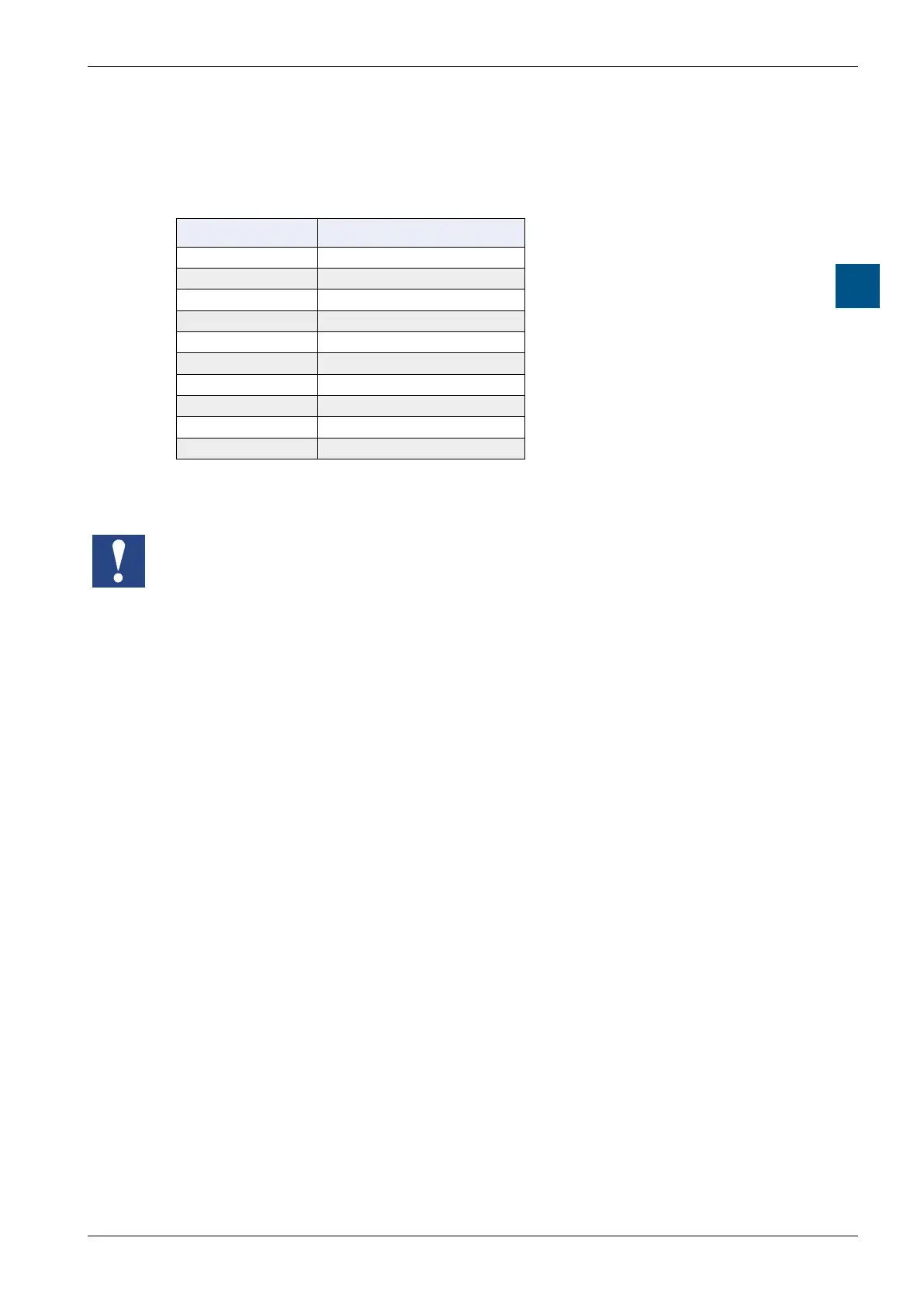
BCD Position Meaning
0 normal read/write**
1 Reserve
2 Reserve
3 Reserve
4 Reserve
5 format * / **
6 Reserve
7 Reserve
8 Reserve
9 normal read only
* Starts after plugging in; pull, then plug in again
** if the card itself is not write-protected (switch or software)
Note
● APClesystemFAT(FAT16)mustbepresentonthecard,sothattheSD
cardcanbeformattedwiththeSBClesystem
● First,allFATlesaredeleted,thentheSBClesystemisinstalledwhen
inserting the card and BCD switch position 5
● IftheBCDswitchisinthe0position,theSBClesystem(SBCNTFS.FFS)
will be installed if it is not already present and the card is empty. Therefore, if
a new card is inserted, it does not need to be formatted with position 5
● Notallashcardshaveawrite-protectswitch
● The card is in a so-called push-push socket (push to pull and plug in)
● All operations except formatting are disabled when the label clip is removed
● Do not pull the card while the busy LED is lit.