Installation manual
HB-37420-810-01-25F-EN PSC1-C-100 Installation manual - V2.2.docx Page 29 of 201
Version: 25F
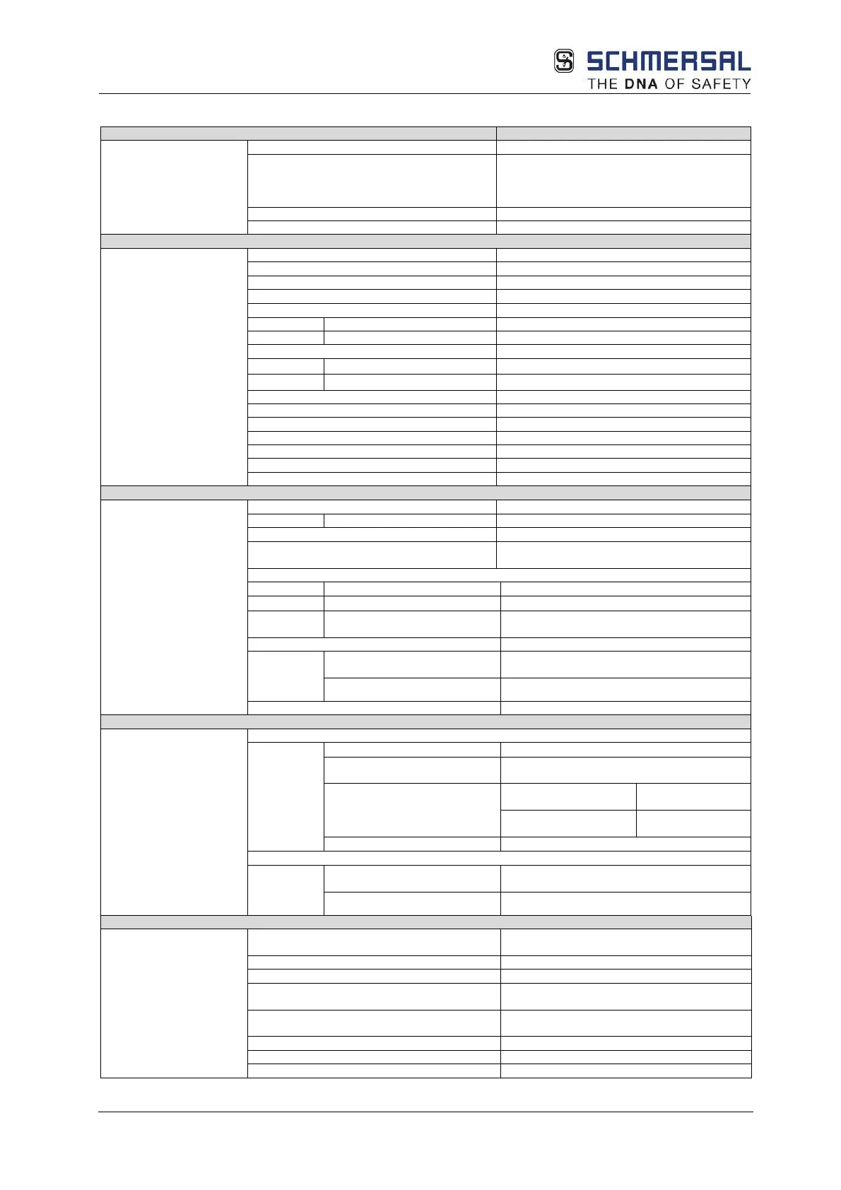
3.7.2.5.1 Tech. characteristic data: PSC1-E-131 and PSC1-E-133
related characteristic data
PL according to EN ISO 13849
PFH
(1)
/architecture 9.2 * 10
-9
/KAT 4
+ on PSC1-E-133
1-channel per relay 2 * 10
-8
(KAT 1)
-9
SIL according to EN 61508
20 years = max. service life
Max. number of expansion modules
Interface for expansion modules
bus connector, can be plugged into DIN rail
Number of safe digital outputs -
Number of safe digital I/O
Number of relay outputs (1
PSC1-E-131
-
PSC1-E-133
4
Number of safe analogue inputs
Removable screw terminals
(D-Sub / screw terminals)
(See table Encoder specifications)
Supply voltage
(tolerance)
24 VDC; 2A
(-15%, +20%)
Max. power consumption (logic)
Rated data digital inputs 24 VDC / 20 mA, type 1 according to EN61131-
Rated data digital outputs
Signal outputs 24 VDC; 250mA
Pulse outputs
24 VDC; 250mA
Digital I/O 00 – 04
24 VDC; 0.5A
NO DC13
24 VDC; 2A
NC DC13
(readback contact)
24 VDC; 2A
Rated data analogue inputs
Electrical data (only for
Rated data digital outputs
Auxiliary outputs
24 VDC; 250mA (G.P.)
Digital I/O 00 – 04
24 VDC; 0.5A (G.P.)
05 – 09 Temperature rating
24 VDC; 2A (G.P.)
Temperature rating
24 VDC; 1.8A
Max. cumulative current
10A
Normally open contact
24 VDC; 2A (Pilot Duty)
Normally closed
24 VDC; 2A (Pilot Duty)
Temperature 0°C … +50°C operation
3k3 according to DIN 60 721
Minimum, maximum relative humidity
5% - 85%
EMC EN 61000-6-2, EN 61000-6-4, EN 61000-6-7,