4
Installation
Braking resistors
Operating Instructions – MOVIDRIVE
®
modular
111
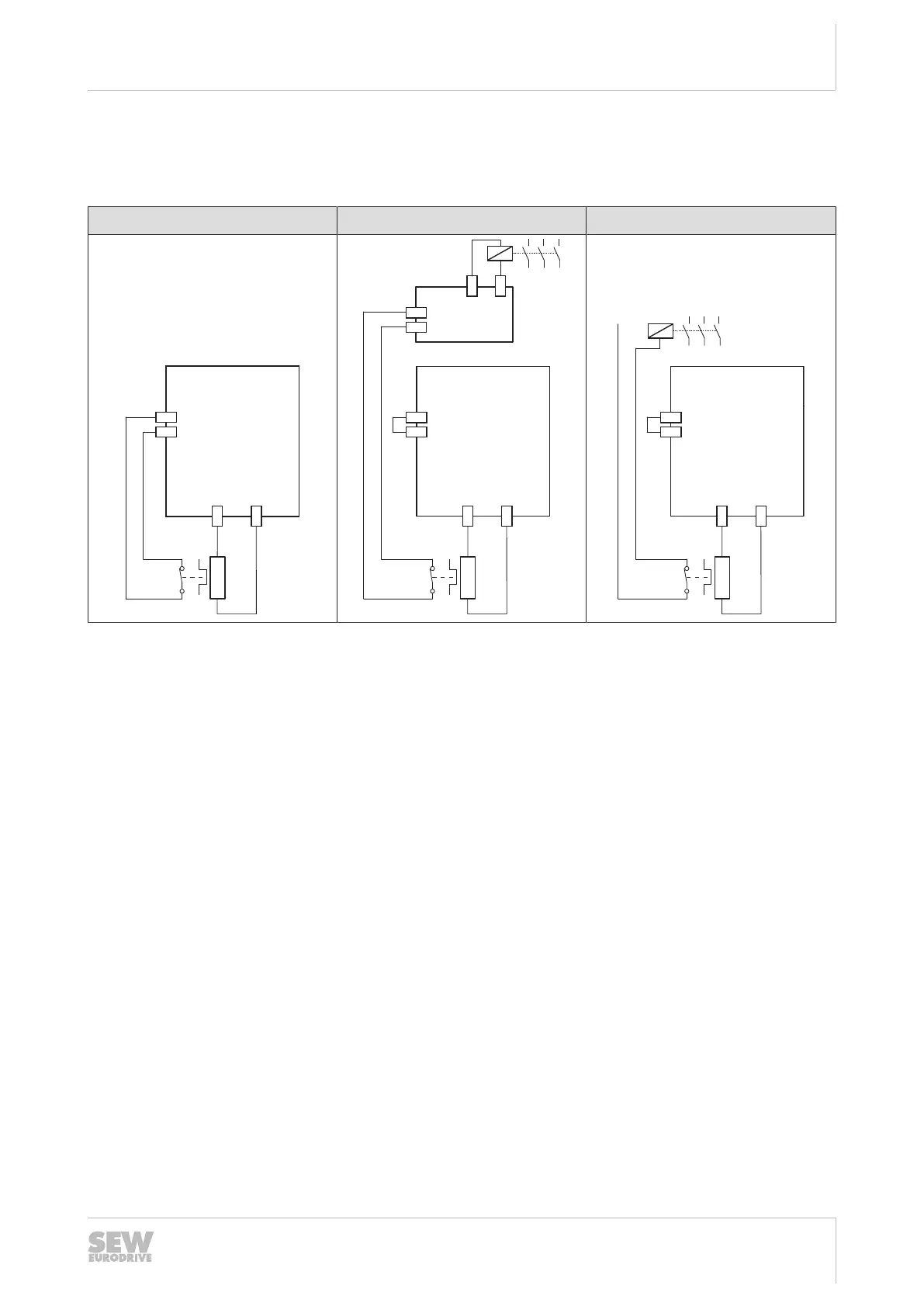
MDP90A-0250, 0500, 0750, 1100 power supply module
If an BW...-T braking resistor with internal temperature switch is used with a 25 –
110kW power supply module, there are 3 possible connections.
Connection 1 Connection 2 Connection 3
MDP90A
X7:2 -Temp_R
X7:1 +Temp_R
[2]
X3 +R
X3 -R
MDP90A
X7:2 -Temp_R
X7:1 +Temp_R
[2]
X3 +R
X3 -R
PLC
DI
24 V OUT
DO
GND
[1]
MDP90A
X7:2 -Temp_R
X7:1 +Temp_R
[2]
X3 +R
X3 -R
[1]
[1] Line contactor
[2] Braking resistor
• Connection 1
– If the thermal circuit breaker trips, the signal in the power supply module is
evaluated.
– This does not require a response by the PLC.
– It is not required to disconnect the supply system connection with an external
switching device.
– If the thermal circuit breaker trips, the power supply module interrupts the
power supply by inhibiting the rectifier.
– If the thermal circuit breaker trips, the power supply module switches all axis
modules to "Output stage inhibit".
• Connection 2
– If the thermal circuit breaker trips, the signal in the PLC is evaluated.
– If the thermal circuit breaker trips, the PLC must interrupt the power supply.
– If the thermal circuit breaker trips, there is no response in the power supply
module and the axis modules.
– With connection 2, it is possible that the PLC finishes the current travel cycle al-
though the thermal circuit breaker has tripped. Only then, the power supply is
disconnected. In this case, the residual braking energy W
Rest
= R
BRnom
× 20 s
must not be exceeded.
• Connection 3
– If the thermal circuit breaker trips, the signal directly affects the line contactor.
24748536/EN – 11/2017
 Loading...