4
Installation
Electrical installation
Operating Instructions – MOVIDRIVE
®
modular
90
4.6.17 Encoder
The encoder cable may include the cables of the temperature evaluation.
For information on the pin assignment, refer to chapter "Terminal assignment at MDA
single-axis module"(→2126).
WARNING
Dangerous contact voltages at the terminals of the application inverter when con-
necting the wrong temperature sensors.
Severe or fatal injuries from electric shock.
• Connect only temperature sensors with protective separation from the motor
winding to the temperature evaluation. Otherwise, the requirements for protective
separation are not met. Dangerous contact voltages may occur at the terminals
of the application inverter via the signal electronics in case of an fault.
Installation notes for encoder connection
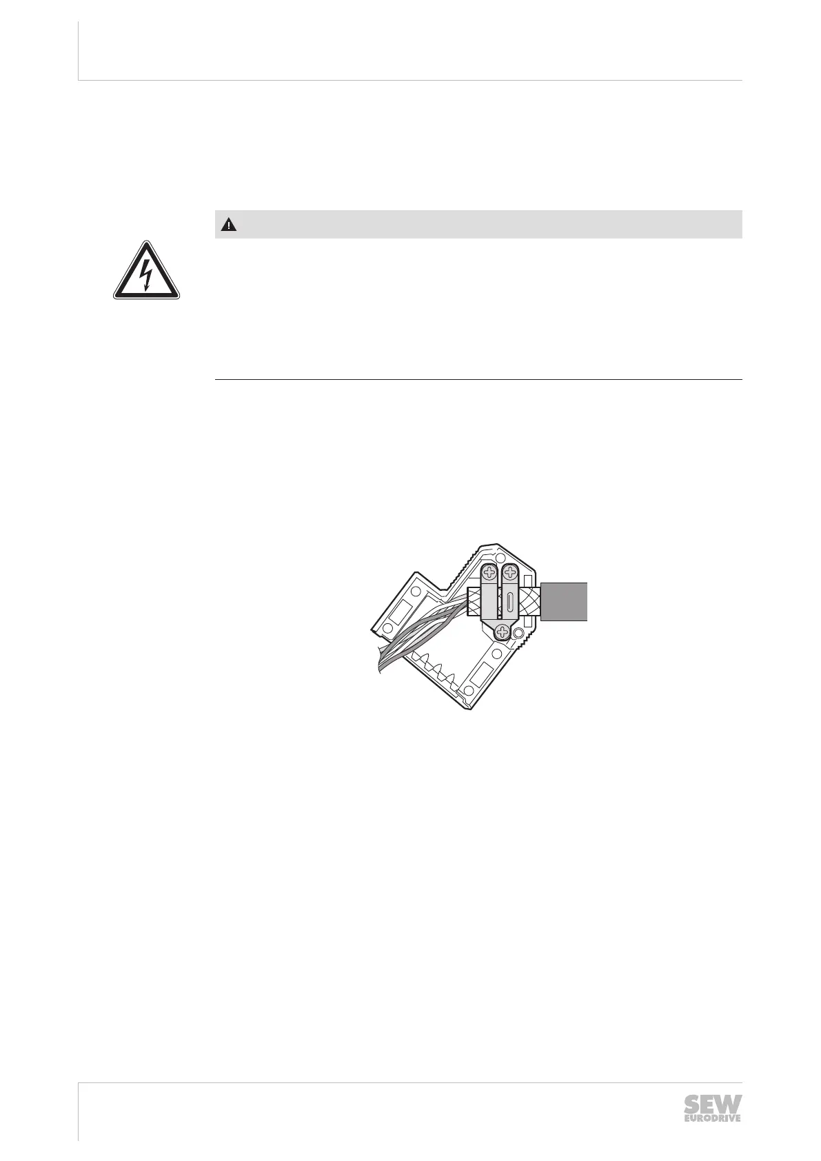
Encoder cable
• Use shielded cables with twisted pair cores. Connect the shield over a wide area
at both ends:
– At the encoder in the cable gland or in the encoder plug,
– At the application inverter in the housing of the D-sub connector.
13887834891
• Route the encoder cable separately from the power cables.
• Connect the shield on the inverter end in the housing of the D-sub connector over
a large area.
On the encoder/resolver
• To ensure a flawless shield connection, an EMC screw fitting must be used for the
cable entry of the signal line.
• For drives with a plug connector, connect the shield on the encoder plug.
Prefabricated cables
SEW‑EURODRIVE offers pre-fabricated cables for connecting encoders.
SEW‑EURODRIVE recommends to use these prefabricated cables.
24748536/EN – 11/2017
 Loading...