4
Installation
Control cabinet installation
Operating Instructions – MOVIDRIVE
®
modular
64
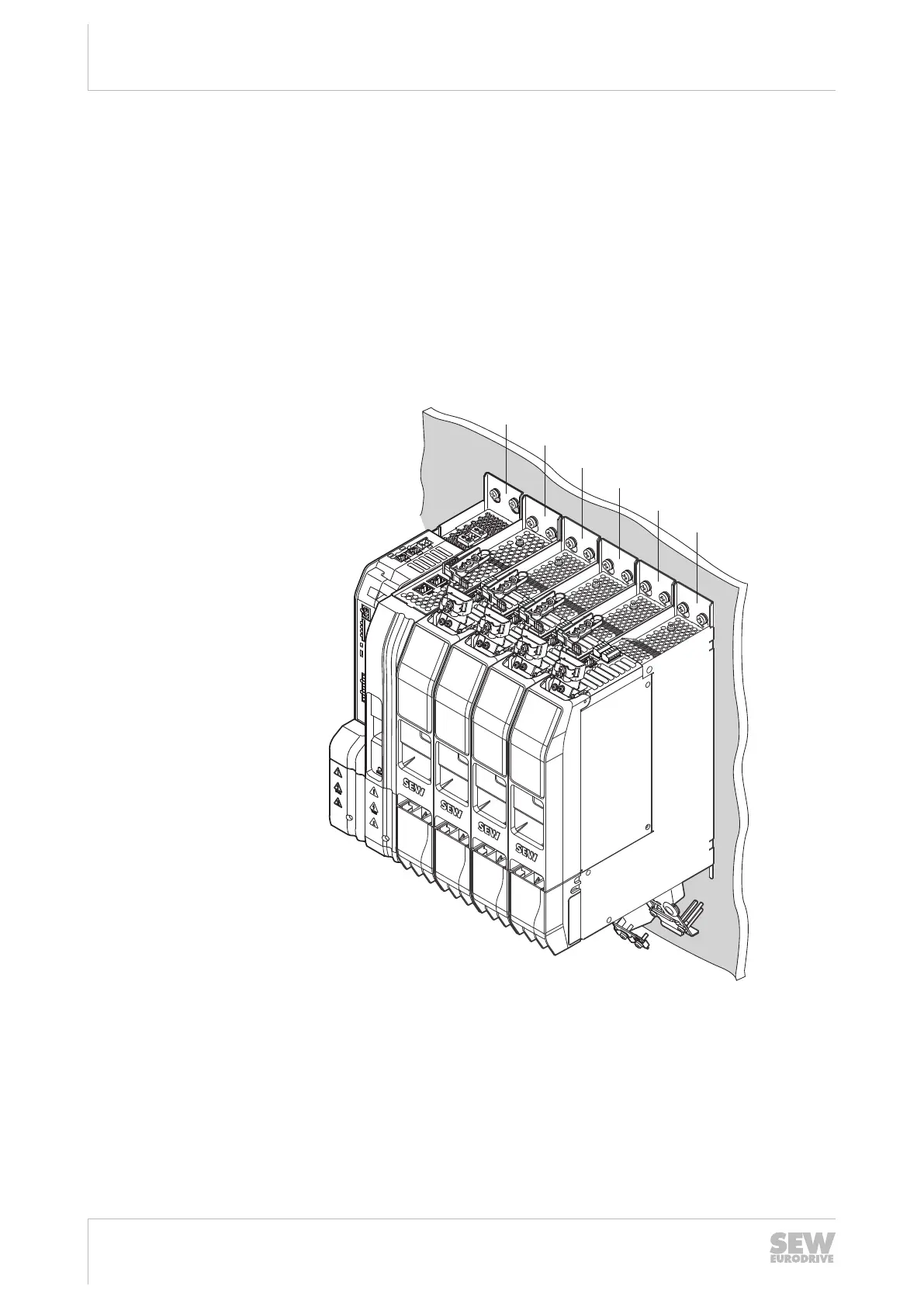
4.5 Control cabinet installation
The following steps are depicted at the example of an axis system with 1 power supply
module, several axis modules, and 1 MOVI-C
®
CONTROLLER.
Other modules are used analogously to the instructions described in this chapter.
4.5.1 Arrangement of the axis modules within the axis system
When arranging the axis system, observe that the nominal output current I
N
of the axis
modules must decrease from left to right. The axis module with the highest nominal
output current must be on the right side of the power supply module. All remaining
axis modules are installed in descending order regarding their nominal output current.
The master module must always be installed on the left of the power supply module.
[1]
[2]
[3]
[4]
[5]
5
4
3
2
1
5
4
3
2
1
5
4
3
2
1
5
4
3
2
1
5
4
3
2
1
5
4
3
2
1
5
4
3
2
1
[6]
20806249227
[1] Master module [4] Example: MDD90A-0040... double-axis module: I
N
=
2 × 4A = 8A
[2] Power supply module [5] Example: MDA90A-0040... single-axis module: I
N
=
4A
[3] Example: MDA90A-0120... single-axis
module: I
N
= 12A
[6] Example: MDA90A-0020... single-axis module: I
N
=
2A
In one axis system, up to 15 axis modules can be used, both as single-axis modules
and double-axis modules.
24748536/EN – 11/2017
 Loading...