4
Installation
Control cabinet installation
Operating Instructions – MOVIDRIVE
®
modular
70
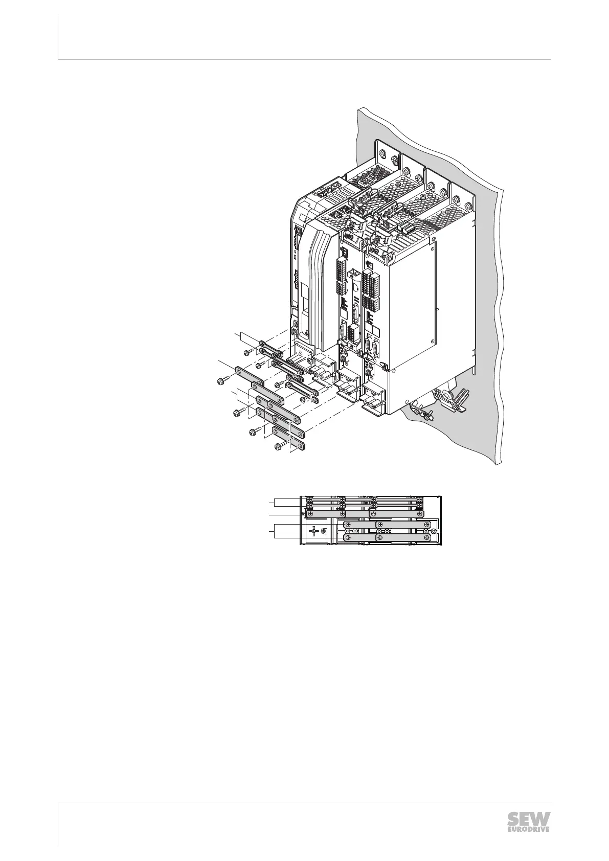
4.5.6 Installing the busbar
+UZ
-UZ
X4
+UZ-UZ
24V
X5
+UZ
X4
-UZ
-UZ +UZ
GND
+UZ
X4
X5
24V
GND
-UZ
+ UZ- UZ
[3]
5
4
3
2
1
5
4
3
2
1
5
4
3
2
1
24V
X5
GND
[1]
[2]
[1]
[2]
[3]
20807025291
1. Install the busbar [1] for the 24V supply voltage as shown in the figure. Tighten
the screws with the specified tightening torque (→252).
2. Install the busbar [2] for the PE connection as shown in the figure. Tighten the
screws with the specified tightening torque (→252).
3. Install the busbar [3] for the DC link connection X4 as shown in the figure. Tighten
the screws with the specified tightening torque (→252).
24748536/EN – 11/2017
 Loading...