9
Functional safety
Safety Conditions
Operating Instructions – MOVIDRIVE
®
modular
258
9.3.4 Requirements on startup
• To validate the implemented drive safety functions, they must be documented and
checked after successful startup (validation).
• Observe the restrictions for drive safety functions in chapter "Restrictions" for the
validation of the safety functions. Non-safety-related parts and components that af-
fect the result of the verification test (e.g. motor brake) must be deactivated, if ne-
cessary.
• For using the application inverter in safety-relevant applications, it is essential that
you perform and record startup checks for the disconnecting device and correct
wiring.
9.3.5 Requirements on operation
• Operation is only allowed within the limits specified in the data sheets. This prin-
ciple applies to the external safety controller as well as the application inverter and
approved options.
• The built-in diagnostic function is limited in case of a permanently enabled or per-
manently disabled STO input. Only with a level change of the STO signal, exten-
ded diagnostic functions are performed. This is why the drive safety function via
STO input must be triggered with connected line voltage at least once every 12
months for PL d according to EN ISO 13849‑1 and SIL 2 EN 61800-5-2 and at
least once every 3 months for PL e according to EN ISO 13849‑1 and
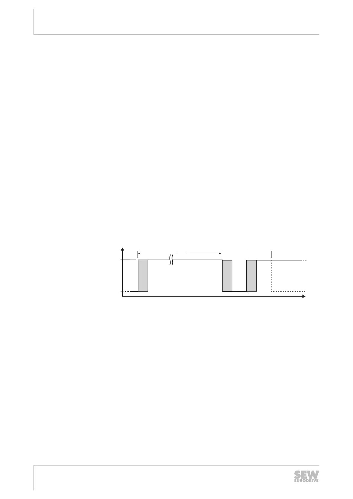
SIL3EN61800‑5‑2 to achieve a complete test coverage. Adhere to the following
test procedure.
[1]
> 700 ms
> 700 ms
[3]
t
[2] [2] [2]
[4]
15205932683
[1] Maximum 12 months with PL d/SIL2
Maximum 3 months with PL e/SIL3
[2] Internal diagnostics
[3] High: No STO
[4] Low: STO active
• To achieve complete test coverage after a device reset (e.g. after connecting the
line voltage), the test transition (STO active → not active) can only be started >
700ms later. The device signals "ready for operation" or "STO – Safe Torque Off"
if it is not in fault state.
• A detected hardware fault in the internal switch-off channels for STO will lead to a
locking fault state of the application inverter. If the fault is reset (e.g. by switching
the line voltage on/off or by a low level at the STO input for at least 30ms), a com-
plete test with internal diagnostics according to the above mentions test procedure
must be performed. If the fault occurs again, replace the device or contact the
SEW‑EURODRIVE Service.
24748536/EN – 11/2017
 Loading...