4
Installation
Mechanical installation
Operating Instructions – MOVIDRIVE
®
modular
53
4.3 Mechanical installation
CAUTION
Risk of injury to persons and damage to property.
Never install defective or damaged application inverters.
• Before installing modules, check them for external damage. Replace any dam-
aged modules.
NOTICE
Risk of damage to property due to mounting surface with poor conductivity.
Damage to the application inverter.
• The mounting plate in the control cabinet must be conductive over a large area
for the mounting surface of the application inverter (metallically pure, good con-
ductivity). EMC compliant installation of the application inverter can only be ac-
complished with a mounting plate that is conductive over a large area.
4.3.1 Hole pattern
Preparing the con-
trol cabinet
You can prepare the control cabinet for the installation of differently assembled axis
systems by drilling tapped holes every 30mm for mounting the modules. The modules
can be attached to this grid irrespective of their width, see figure below.
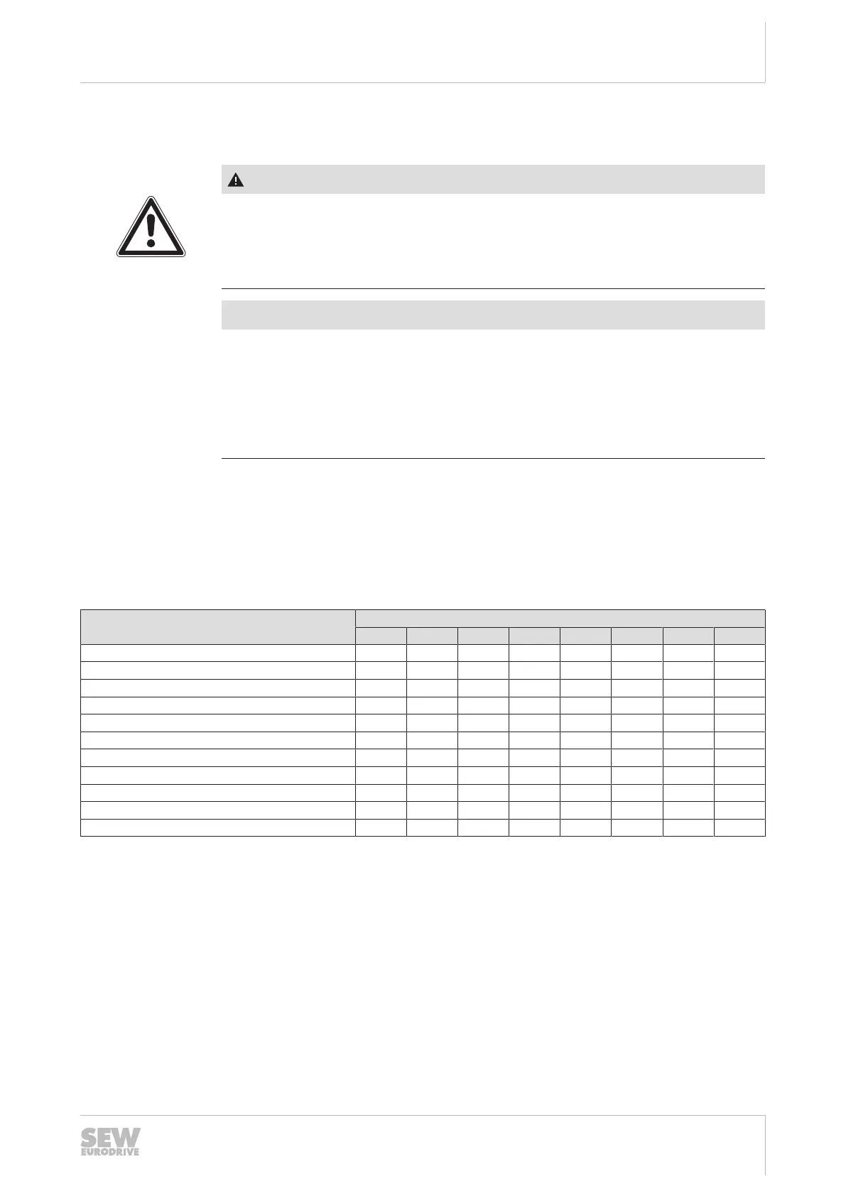
Dimensions
Device base plate
Modules Dimensions of the device base plate in mm
A B C D E F G H
MDP90A-0100 (size 1) 60 30 355 383 19 15 7 13
MDP90A-0100 (size 1a) 120 90 355 383 19 15 7 13
MDP90A-0250 (size 2) 60 30 455 483 19 15 7 13
MDP90A-0500, 0750 (size 3) 150 120 433 473 28 15 7 13
MDA90A-0020, 0040, 0080, 0120 (size 1) 60 30 355 383 19 15 7 13
MDA90A-0160, 0240 (size 2) 90 60 355 383 19 15 7 13
MDA90A-0320, 0480 (size 3) 90 30 455 483 19 15 7 13
MDA90A-0640, 1000 (size 5) 150 120 455 483 19 15 7 13
MDD90A-0020, 0040 (size 1) 60 30 355 383 19 15 7 13
MDD90A0020, 0040, 0080 (size 2) 90 60 355 383 19 15 7 13
MDM90A 60 30 355 383 19 15 7 13
24748536/EN – 11/2017
 Loading...