6
Operation
Axis module fault
Operating Instructions – MOVIDRIVE
®
modular
168
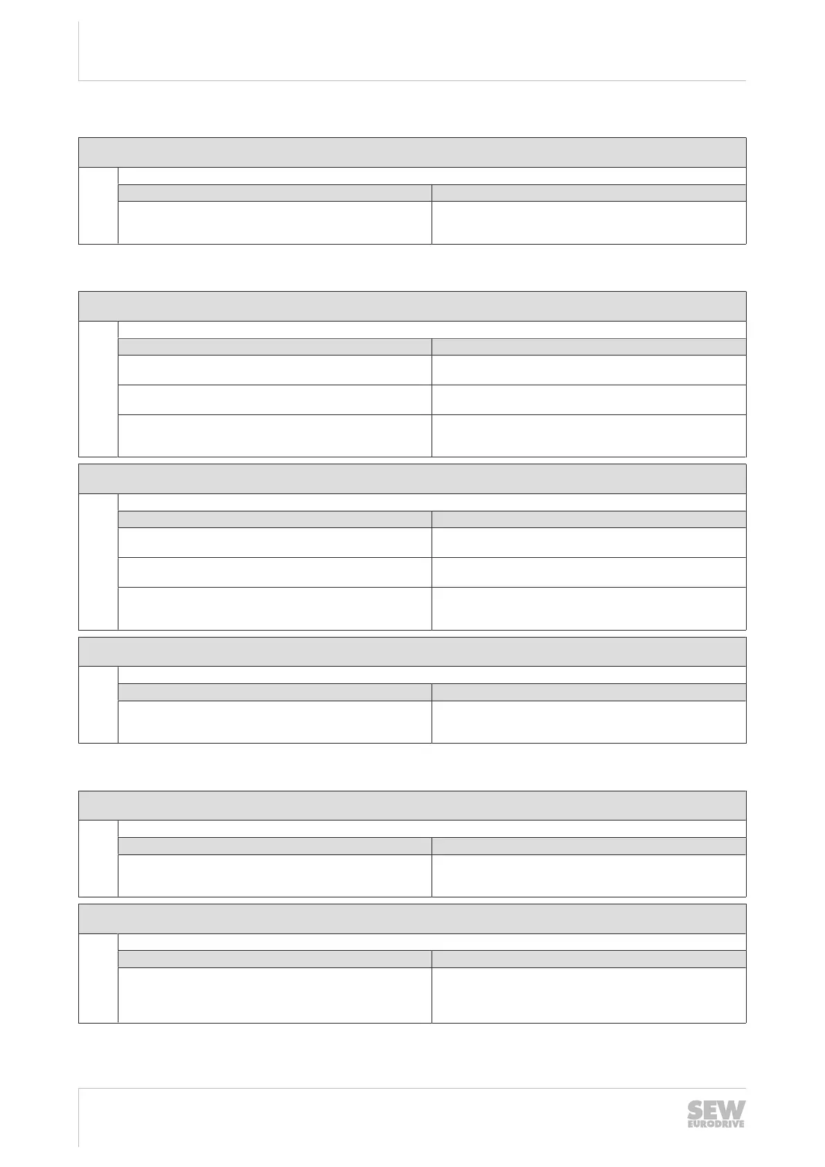
6.5.5 Fault 7 DC link fault
Subfault: 7.1
Description: DC link overvoltage
Response: Output stage inhibit
Cause Measure
The maximum permitted DC link voltage limit was exceeded,
and the output stage was inhibited by the hardware.
– Extend deceleration ramps.
– Check supply cable to the braking resistor.
– Check technical data of the braking resistor.
6.5.6 Fault 8 Speed monitoring fault
Subfault: 8.1
Description: Speed monitoring – motor mode
Response: Output stage inhibit
Cause Measure
The speed controller operates at setting limit (mechanical over-
load or phase failure in supply system or motor).
Increase the delay time set for speed monitoring, or reduce the
load.
Encoder not connected correctly Check encoder connection and direction of rotation. If neces-
sary, increase current limiting or reduce acceleration values.
Encoder has incorrect direction of rotation Check encoder connection and direction of rotation. If neces-
sary, increase current limiting or reduce acceleration values.
– Check motor lead and motor, check line phases.
Subfault: 8.2
Description: Speed monitoring – generator mode
Response: Output stage inhibit
Cause Measure
The speed controller operates at setting limit (mechanical over-
load or phase failure in the supply system or the motor).
Increase the delay time set for speed monitoring, or reduce the
regenerative load.
Encoder not connected correctly Check encoder connection and direction of rotation. If neces-
sary, increase current limiting or reduce deceleration values.
Encoder has incorrect direction of rotation – Check encoder connection and direction of rotation. If neces-
sary, increase current limiting or reduce deceleration values.
– Check motor cable and motor. Check line phases.
Subfault: 8.3
Description: Maximum speed at motor shaft
Response: Output stage inhibit
Cause Measure
Actual speed exceeded "Maximum speed at motor shaft" limit
(index 8360.9/8361.9). This limit value is set at startup match-
ing motor and gear unit.
Reduce the maximum speed.
6.5.7 Fault 9 control mode
Subfault: 9.1
Description: Magnetization of motor not possible
Response: Output stage inhibit
Cause Measure
User current limit or output stage monitoring reduced possible
maximum current to such a degree that required magnetizing
current cannot be set.
– Reduce output stage utilization (e.g. by reducing the PWM
frequency or by reducing the load).
– Increase the user current limit.
Subfault: 9.2
Description: Requested operating mode not possible with active control mode
Response: Output stage inhibit
Cause Measure
The current FCB has activated an operating mode. The active
control mode does not support this operating mode, for ex-
ample "position control" or "torque control" with V/f control
mode.
Start up control mode that supports the required operating
mode. Connect encoder is necessary. Select an operating
mode that is supported by the current control mode.
24748536/EN – 11/2017
 Loading...