4
Installation
Braking resistors
Operating Instructions – MOVIDRIVE
®
modular
113
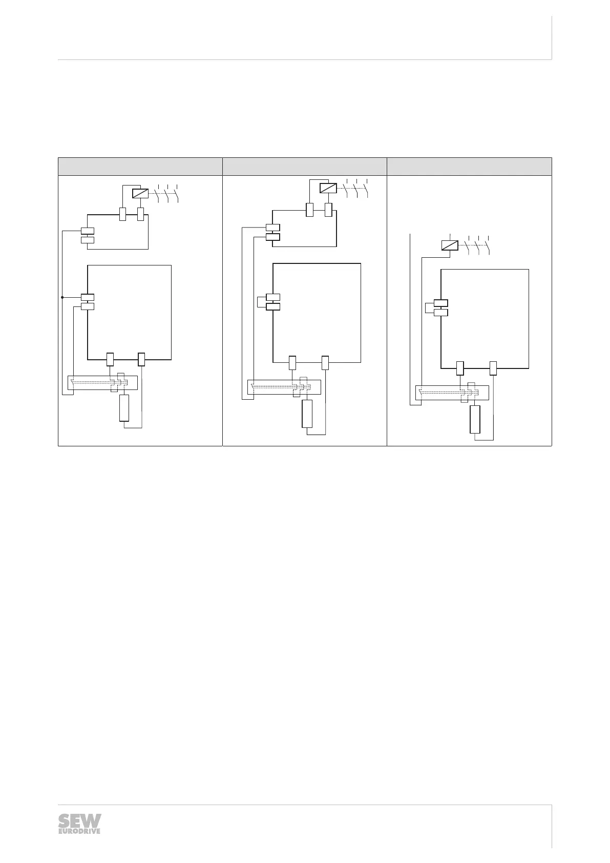
External bimetallic relay
MDP90A-0100-.. power supply module
If an external bimetallic relay is used with a 10kW power supply module, there are 3
possible connections.
Connection 1 Connection 2 Connection 3
MDP90A
X7:2 -Temp_R
X7:1 +Temp_R
[2]
X3 +R
X3 -R
PLC
DI
24 V OUT
DO
GND
[1]
9007214215763467
MDP90A
X7:2 -Temp_R
X7:1 +Temp_R
X3 +R
X3 -R
[2]
PLC
DI
24 V OUT
DO
GND
[1]
MDP90A
X7:2 -Temp_R
X7:1 +Temp_R
X3 +R
X3 -R
[2]
[1]
[1] Line contactor
[2] Braking resistor
Note that the reference potential GND of the digital input control must be the same as
the reference potential of the application inverter when connection 1 is used.
• Connection 1
– If the thermal circuit breaker trips, the signal in the power supply module and in
the PLC is evaluated.
– If the thermal circuit breaker trips, the PLC must interrupt the power supply.
– If the thermal circuit breaker trips, the power supply module switches all axis
modules to "Output stage inhibit".
• Connection 2
– If the thermal circuit breaker trips, the signal in the PLC is evaluated.
– If the thermal circuit breaker trips, the PLC must interrupt the power supply.
– If the thermal circuit breaker trips, there is no response in the power supply
module and the axis modules.
– With connection 2, it is possible that the PLC finishes the current travel cycle al-
though the thermal circuit breaker has tripped. Only then, the power supply is
disconnected. In this case, the residual braking energy W
Rest
= P
BRnom
× 20 s
must not be exceeded.
• Connection 3
– If the thermal circuit breaker trips, the signal directly affects the line contactor.
24748536/EN – 11/2017
 Loading...