MX-M264U TROUBLESHOOTING 7 – 24
3. Image send communication report code
A. Outline and code system descriptions
After completion of communication, the communication report
table, the communication management table, and the protocol are
described on the communication report column.
The communication report code is composed as follows:
Communication report: XX (XXXX)
The upper 2 digits of the communication report code:
Communication report code of 00 – 99 (Refer to communication
report main code.)
The lower 4 digits of the communication report code:
Used by the serviceman.
The upper 2 digits: Communication report sub code 1 (Refer to
communication report sub code 1.)
The lower 2 digits: Communication report sub code 2 (Refer to
communication report sub code 2.)
CAUTION: The communication report sub code 1 and sub code 2
are in hexadecimal notation. (The others are in decimal
notation.)
CAUTION: The communication report sub code 1 is not used in the
these models.
B. Details
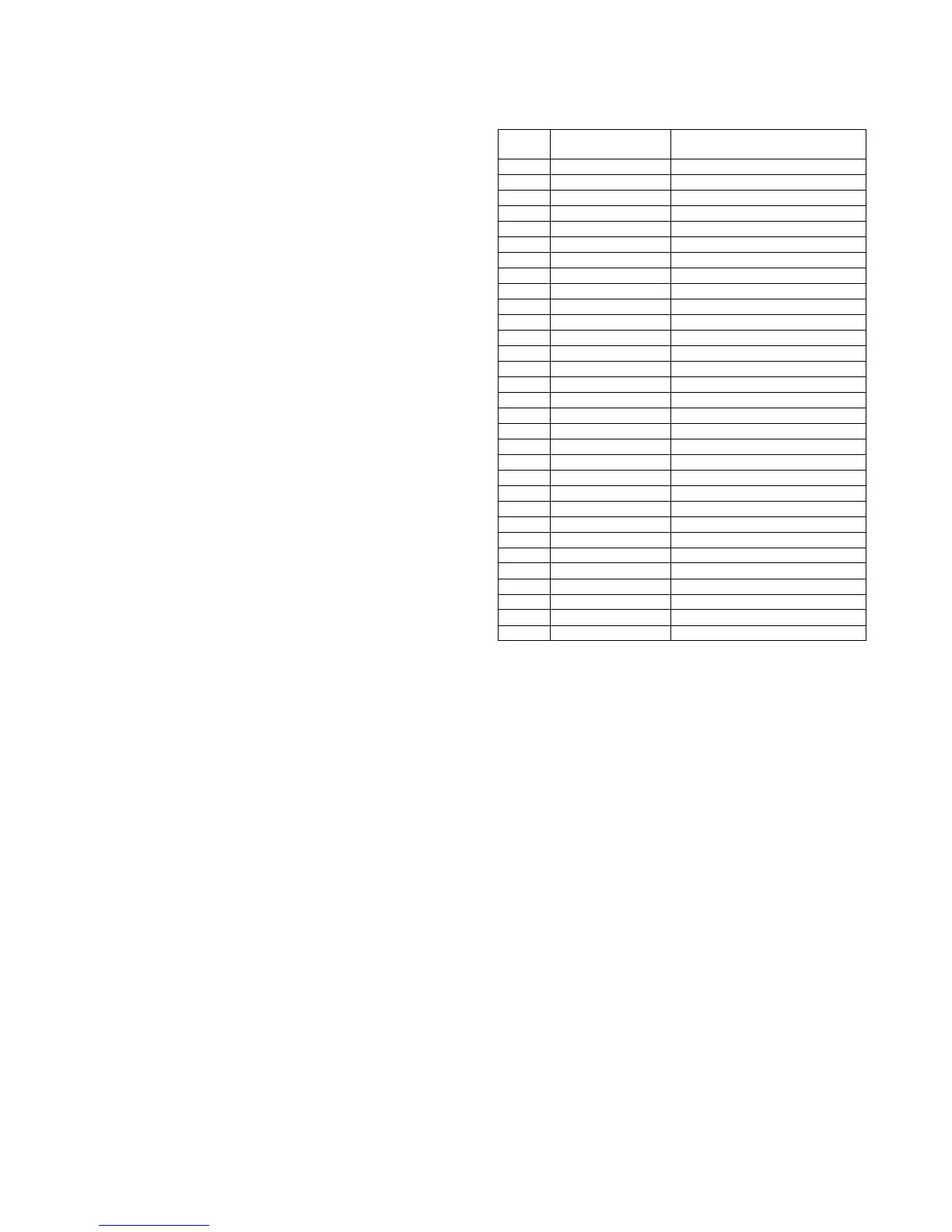
(1) Communication report main code
CAUTION: For report codes 16 – 31, V.34 MODE COMMUNICA-
TION.
Report
code
Final receive signal
(Send side)
Final receive signal (Receive side)
0 Abnormal signal Abnormal signal
1 NSF, DIS (SID), (SUB), NSS, DCS
2 CFR (PWD), (SEP), NSC, DTC
3 FTT EOP
4MCF EOM
5 PIP, PIN MPS
6RTN, RTP PRI-Q
7 No signal, DCN DCN
8 PPR PPS-EOP
9 PPS-EOM
10 PPS-MPS, PPS-NULL
11 RNR RR
12 CTR CTC
13 ERR EOR-Q
14 PPS-PRI-Q
16 Abnormal signal Abnormal signal
17 NSF, DIS SID, SUB, NSS, DCS
18 CFR PWD, SEP, NSC, DTC
19 FTT PPS-EOP
20 MCF PPS-EOM
21 PIP, PIN PPS-MPS, PPS-NULL
22 RTN, RTP PRI-Q
23 No signal, DCN DCN
24 PPR
25 RNR RR
26 CTR CTC
27 ERR EOR-Q
28 PPS-PRI-Q
29 V.8 Phase-1 V.8 Phase-1
30 V.8 Phase-2 V.8 Phase-2
31 V.8 Phase-3 V.8 Phase-3