MX-M264U ADJUSTMENTS AND SETTINGS 5 – 35
ADJ 15 Copy image position and image
loss adjustment
(Manual adjustment)
NOTE: Normally if the adjustment is executed by ADJ 3 (automatic
adjustment), there is no need to execute this adjustment.
Only when the manual adjustment is required, execute this
adjustment.
In other words, this manual adjustment is executed when a
satisfactory result is not obtained from the automatic
adjustment (ADJ 3).
15-A Copy image position, image loss, and void
area adjustment (Manual adjustment)
(Document table mode)
This adjustment must be performed in the following cases:
* When the scanner (reading) section is disassembled.
* When the scanner (reading) unit is replaced.
* When the LSU is replaced or removed.
* When the registration roller section is disassembled.
* U2 trouble has occurred.
* The PCU PWB has been replaced.
* The EEPROM of the PCU PWB has been replaced.
* The scanner control PWB has been replaced.
* The EEPROM on the scanner control PWB has been replaced.
NOTE: Before executing this adjustment, be sure to confirm that
the ADJ 3 Print engine image skew, image position, image
magnification ratio, void area adjustments has been com-
pleted normally.
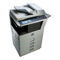
1) Place a scale on the document table as shown in the figure
below.
Place a scale so that it is in parallel with the scanning direction
and that its lead edge is in contact with the document guide
plate.
Place white paper on the document table so that the scale lead
edge can be seen.
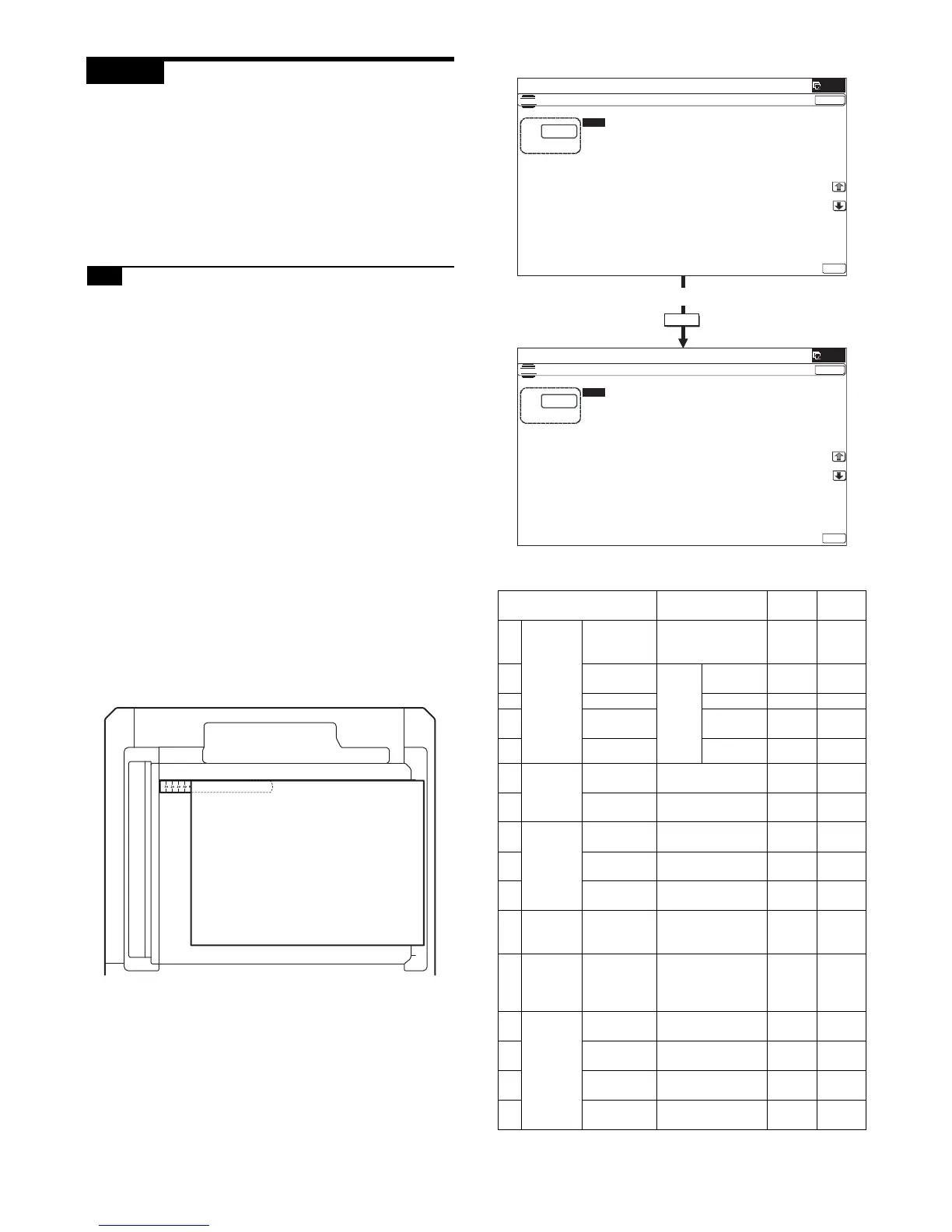
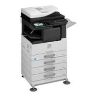
2) Enter the SIM 50-1 mode.
3) Set RRCA, LEAD, and SIDE to the default values.
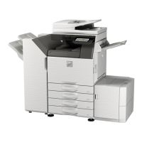
Item/Display Content
Setting
range
Default
value
A Lead
edge
adjust-
ment
value
RRCA Document lead
edge reference
position (OC)
0 - 99 50
B RRCB-CS12 Regis-
tration
motor
ON
timing
adjust-
ment
Standard
Tray
1 - 99 50
C RRCB-DSK Desk 1 - 99 50
D RRCB-MFT Manual
paper feed
1 - 99 50
E
RRCB-ADU
ADU 1 - 99 50
FImage
loss area
setting
value
LEAD Lead edge image
loss area setting
0 - 99 40
G SIDE Side image loss
area adjustment
0 - 99 20
H Void area
adjust-
ment
DENA Lead edge void
area adjustment
1 - 99 30
I DENB Rear edge void area
adjustment
1 - 99 30
J FRONT/
REAR
FRONT/REAR void
area adjustment
1 - 99 20
K Off-center
adjust-
ment
OFFSET_
OC
OC document off-
center adjustment
1 - 99 50
L Magnifi-
cation
ratio
correction
SCAN_
SPEED_OC
SCAN sub scanning
magnification ratio
adjustment (CCD)
1 - 99 50
M Sub
scanning
direction
print area
correction
value
DENB-MFT Manual feed
correction value
1 - 99 57
N DENB-CS1 Tray 1 correction
value
1 - 99 50
O DENB-CS2 Tray 2 correction
value
1 - 99 57
P DENB-CS3 Tray 3 correction
value
1 - 99 57
OK
10-key