MX-M264U EXTERNAL VIEW AND INTERNAL STRUCTURE 4 – 2
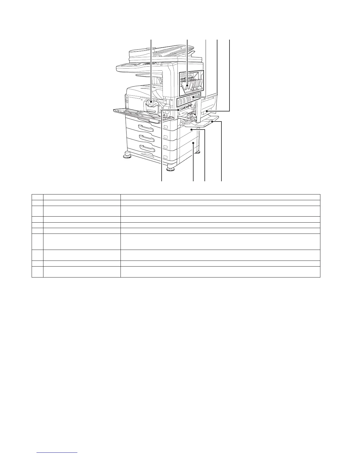
2. Internal structure
No. Name Function/Operation
1 Toner cartridge This holds toner for printing. The toner cartridge must be replaced when indicated on the operation panel.
2 Upper cover of machine Open this cover to remove jam paper when a paper jam occurs in the output of the job separator or the optional
finisher.
3 Fusing unit Heat is applied here to fuse the transferred image onto the paper.
4 Right side cover Open this cover to remove a misfeed.
5 Right side cover release lever To remove a paper misfeed, pull and hold this lever up to open the right side cover.
6 Photoconductive drum This drum has a photoconductive coating on its surface.
The images are formed on top of this photoconductive surface.
(The photoconductive coating is green in color.)
7 Right cover of paper drawer (when a
paper drawer is installed)
Open this to remove a paper misfeed in tray 3 or tray 4.
8 Paper tray right side cover Open this to remove a paper misfeed in tray 2.
9 Bypass tray Use this tray to feed paper manually.
When loading a large sheet of paper, be sure to pull out the bypass tray extension.
1 2 3
8 976
54