MX-M264U ADJUSTMENTS AND SETTINGS 5 – 38
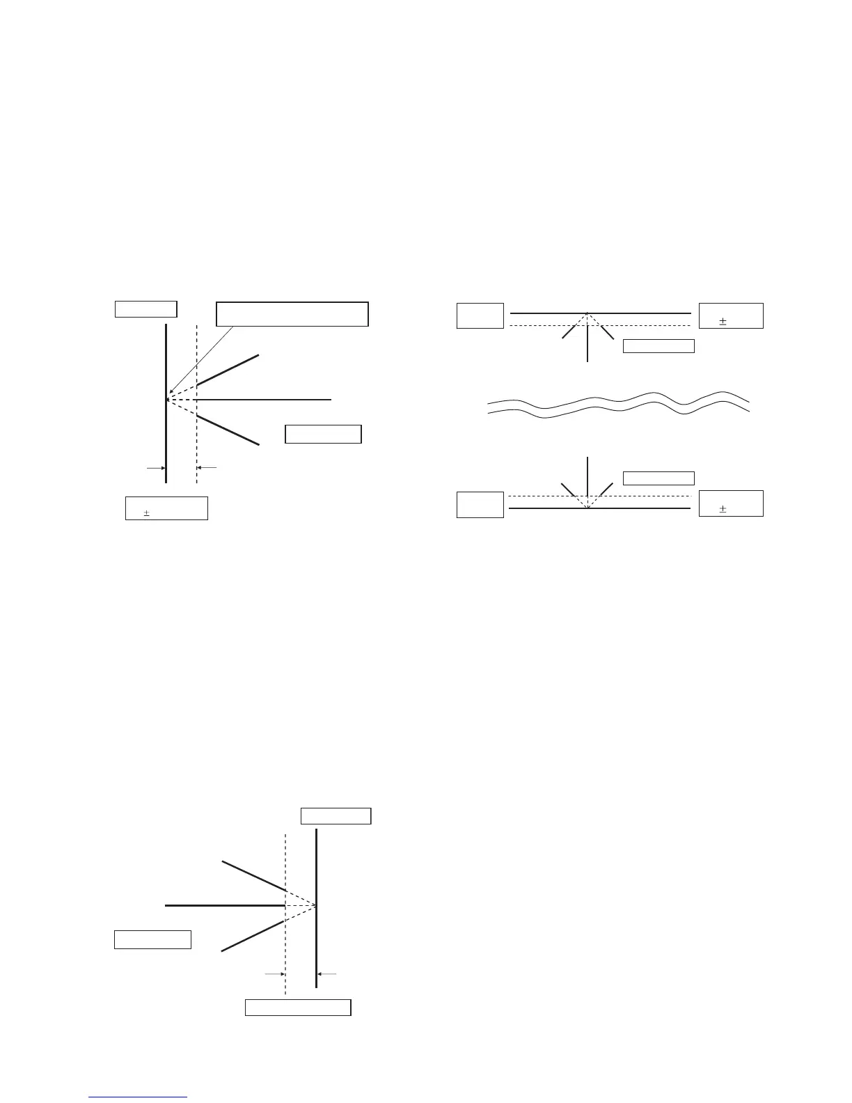
Lead edge image loss adjustment
1) Set the lead edge image loss adjustment values (LEAD EDGE
(SIDE1/SIDE2) on the front surface and the back surface to
the following values.
(Standard set value)
TRAIL EDGE (SIDE 1):
40 Lead edge image loss set value (Front surface)
TRAIL EDGE (SIDE 2):
40 Lead edge image loss set value (Back surface)
(When the set value is increased, the lead edge image loss is
increased.)
(Change for change in the set value: 0.1mm/step)
2) Make a duplex copy in 100% in the RSPF mode. Check to
confirm that the lead edge image loss is within 4.0 1.0mm on
the front surface and the back surface. The paper lead edge
must be aligned with the presumed image lead edge.
If the above condition is not satisfied, perform the following
procedure.
3) Enter the adjustment value of SIDE1/SIDE2 with 10-key, and
press [OK] key.
Adjust so that the paper lead edge is aligned with the pre-
sumed image lead edge.
SIDE1: Front surface lead edge scan position adjustment
SIDE2: Back surface lead edge scan position adjustment
(When the adjustment value is increased, the print image posi-
tion is shifted to the delaying direction for the paper.)
(Change for change in the set value: 0.1mm/step)
Perform the procedures of 2) - 3) until a satisfactory result is
obtained.
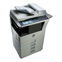
Rear edge image loss adjustment
1) Make a duplex copy in 100% in the RSPF mode. Check to
confirm that the rear edge image loss is 2.0 - 5.0mm on the
front surface and the back surface.
If the above condition is not satisfied, perform the following
procedure.
2) Enter the adjustment value of TRAIL EDGE (SIDE1/SIDE2)
with 10-key, and press [OK] key.
TRAIL EDGE (SIDE 1):
Rear edge image loss adjustment value (Front surface)
TRAIL EDGE (SIDE 2):
Rear edge image loss adjustment value (Back surface)
(When the adjustment value is increased, the rear edge image
loss is increased.)
(Change for change in the set value: 0.1mm/step)
Perform the procedures of 1) - 2) until a satisfactory result is
obtained.
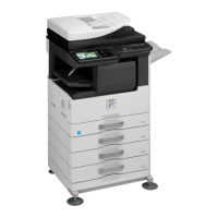
Front/rear frame direction image loss adjustment
1) Make a duplex copy in 100% in the RSPF mode. Check to
confirm that the image losses on the front frame side and the
rear frame side are 2.0 2.0mm on the front surface and the
back surface.
If the above condition is not satisfied, perform the following
procedure.
2) Enter the adjustment value of FRONT/REAR (SIDE 1) /
FRONT/REAR (SIDE 2), and press [OK] key.
FRONT/REAR (SIDE 1):
Front/Rear image loss adjustment value (Front surface)
FRONT/REAR (SIDE 2):
Front/Rear image loss adjustment value (Back surface)
(When the adjustment value is increased, the front/rear image
loss is increased.)
(Change for change in the adjustment value: 0.1mm/step)
Perform the procedures of 1) - 2) until a satisfactory result is
obtained.
Paper lead edge
Copyimage
Image loss
4.0 1.0mm
The paper lead edge mustbe alignedwith
theimagelead edge.
Paper rearedge
Copyimage
Image loss 2.0 -5.0mm
Paper F
sideedge
Paper R
sideedge
Copyimage
Copyimage
Image loss
2.02.0mm
Image loss
2.02.0mm