APPENDIX C: CALCULATIONS
Current loading of the Aura Fire Alarm ControlPanel is limited to the capacity of the power supplies. Installers
must determine the loading placed on these power supplies by adding the sum of device loads to the no load
alarm current of the Aura Fire Alarm ControlPanel. The result obtained from this calculation must be below the
operating current of the power supply.
The 5.25 Amp Power Supply operates the fire control panel and external loads with 5.25 Amps and reserves
1.25 Amps for charging the standby batteries.
The 10.25 Amp Power Supply operates the fire control panel and external loads with 10.25 Amps and reserves
2.25 Amps for charging the standby batteries.
Current limits are provided in Specifications for outputs of the Aura Fire Alarm ControlPanel. Total device
currents must be below limits provided for all outputs of the fire control panel.
The calculation of total current loading must include the sum of device loads on the circuit outputs of the Aura Fire
Alarm ControlPanel. Circuits to be included in this calculation for total current loading are:
l SLC Loops
l NAC Outputs
l 24V OUT
l AUX 24V
l Peripheral Interface Modules
l Network Module
l Panel Standby and Alarm Currents
The current limits provided in Specifications are maximums for individual outputs of the fire control panel. These
output-levels are not intended to be summed together to determine the total current available from the Aura Fire
Alarm ControlPanel. Refer to these levels only when determining the limit of device-loading on each output
circuit.
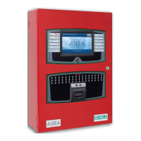
SHIELD Fire, Safety & Security Ltd
Aura Fire Alarm Control Panel Installation Manual
Version 1.00 |June 2019 |MAN-1431VS
Page 142
Appendix C: Calculations