Replacing Cabinet Components
1. Replace the backplate and power supply.
2. Replace the door and fascia.
3. Reconnect the cabling.
Connecting and Dressing Cabling
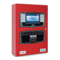
This section describes connections between the power supply and the Main Back Board of the Aura Fire Alarm
ControlPanel. Separate high and low voltage wiring in the enclosure with a minimum gap of 0.25".
Connecting 24V and 14 Conductor Wiring
Refer to Connecting Field Wiring for specific details about proper wiring. To connect 24V wiring of the power
supply to the Main Back Board:
1. Connect the red wire from the positive (+ ) 24V terminal of the power supply to the positive (+ ) terminal
on the Main Back Board.
2. Connect the black wire from the negative (- ) RTN terminal of the power supply to the negative (- )
terminal on the Main Back Board.
3. Connect the 14 Conductor Cable from the power supply to the Main Back Board.
Installing Power Supplies
Aura Fire Alarm ControlPanels can be equipped with either a 5.25 Amp or 10.25 Amp power supply. Set DIP
switches on the 5.25 Amp and 10.25 Amp Power Supplies before completing the installation process. Refer to
DIP Switch Settings. The power supply settings must be performed to establish the optimal charge current of the
standby batteries. These power supplies can be set to operate at an input of 230 VAC. For more information
about the power supplies and their functions, see Power Supplies.
The 5.25 Amp Power Supply
Refer to Connecting Field Wiring for specific details about wiring the power supplies. Provide an AC power
connection to the terminal block from a 15 Amp branch circuit. The following figure illustrates AC connections of
the 5.25 Amp Power Supply:
SHIELD Fire, Safety & Security Ltd
Aura Fire Alarm Control Panel Installation Manual
Version 1.00 |June 2019 |MAN-1431VS
Page 22
Installation