Installing Optional Panel Modules
Panel modules are installed at the factory according to customer requirements. In some situations, it may be
necessary to install additional panel modules to satisfy site configuration requirements. This section describes
procedures for installing and configuring panel modules. Before installing optional panel modules, check and set
the DIPswitch settings, if applicable.
DIP Switch Settings
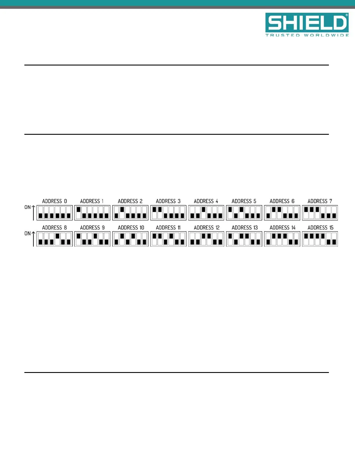
Each panel module of the Aura Fire Alarm ControlPanel must contain a unique setting before being connected
to the Main Back Board. The binary setting of the DIP switch sets the specific address for the panel module. The
numeric order of the address setting between modules does not impact operation, but each panel module must
be assigned a separate / unique address.
The black portion of the DIP switch identifies the switch actuator.
Address 0 is shown above for illustrative purposes only. Address 0 should never be used.
For addresses above 15, switches 5 and 6 will need to be used.
l For address 16-31, switch 5 should be in the ON position. Switch 5 ALONE adds 16 to the address
number. For example, for address 20, set the switch position to address 4 shown above and switch 5 in
the ON position.
l For address 32-47, switch 6 should be in the ON position. Switch 6 ALONE adds 32 to the address
number.
l For address 48-63, switches 5 AND 6 should be in the ON position. Switches 5 and 6 TOGETHER adds
48 to the address number.
Placement
To install modules on the Aura Fire Alarm ControlPanel:
Installation
SHIELD Fire, Safety & Security Ltd
Aura Fire Alarm Control Panel Installation Manual
Version 1.00 |June 2019 |MAN-1431VS
Page 25