When powering these devices, the circuit acts as a Class B pathway only when an EOLR-1 is the last device on
the circuit and the relay contacts are supervised. The wiring loss must not exceed 8V. Refer to the
SystemSensor Installation Instructions for wiring information.
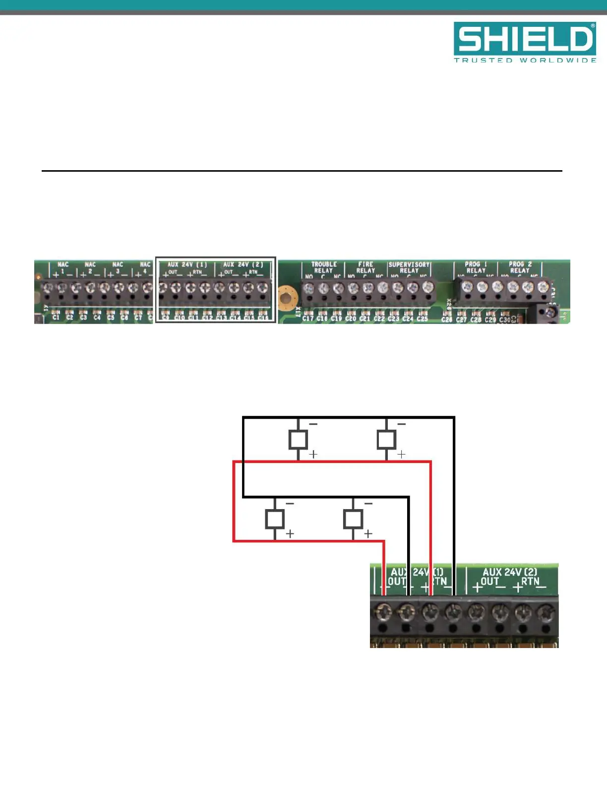
AUX 24V 1 and AUX 24V 2
The AUX 24V output terminals provide regulated, non-programmable 24V DC for powering ancillary devices
such as loop modules, I/O boards, and remote displays. The outputs are fused at 900 mA and include a
maximum load rating of 900 mA. Outputs of AUX 24V 1 and AUX 24V 2 are also supervised for circuit trouble
conditions.
Wiring gauge on AUX 24V 1 or AUX 24V 2 outputs must be sized as a function of cable length and device load to
ensure that voltage-drop of the cable does not result in less than the minimum operating voltage at the ancillary
devices.
Connect the ancillary devices to the
OUTterminals. The OUTterminals
supply 24V power and provide short
circuit monitoring.
Connect RTNterminals to the last
ancillary device. The RTNterminals
provide open circuit monitoring.
If open circuit monitoring is not
required, the RTNterminals must be
connected to the OUT terminals to
prevent reporting of
OPENCIRCUITTROUBLE.
This illustrates a Class B circuit that provides open circuit monitoring.
Installation
SHIELD Fire, Safety & Security Ltd
Aura Fire Alarm Control Panel Installation Manual
Version 1.00 |June 2019 |MAN-1431VS
Page 39