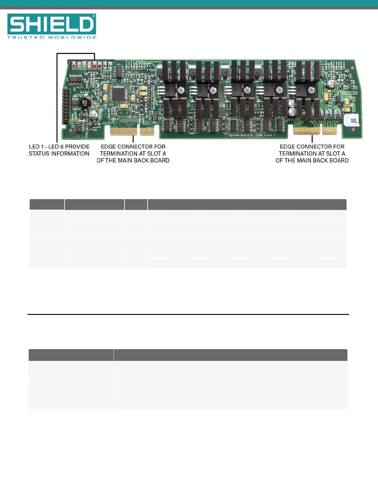
System A Panel Module fits into slot A of the Back Board and contains power supply monitoring, trouble
monitoring, and four NAC circuits.
LED Label Name Color Description
LED 1 Heartbeat Red Identifies functional status of System A Panel Module.
LED 2 Rx Comms Green A blinking green light indicates that the module is receiving data.
LED 3 Tx Comms Green A blinking green light indicates that the module is transmitting data.
LED 4 Trouble Yellow A flashing yellow identifies an error condition.
LED 5 Input Active LED Red Indicates that an input is active.
LED 6 Output Active LED Red Indicates that an output is active.
System B Panel Module (AUL-9070)
System B Panel Module monitors and controls essential input and output functions on the Aura Fire Alarm
ControlPanel. The System B Panel Module includes the following input and output functions:
Input and Output Functions Description
AUX 24 Output 1 24V DC output
AUX 24 Output 2 24V DC output
Fire Routing Output 2 0V output in standby, switches to 24V when activated, requires End-of-Line (EOL) diode
Fire Routing Input Supervised input, requires 3.3K Ohm EOL resistor
Trouble Routing Output 24V output in standby, switches to 0V when activated, requires 3.3K Ohm EOL resistor
SHIELD Fire, Safety & Security Ltd
Aura Fire Alarm Control Panel Installation Manual
Version 1.00 |June 2019 |MAN-1431VS
Page 54
Overview