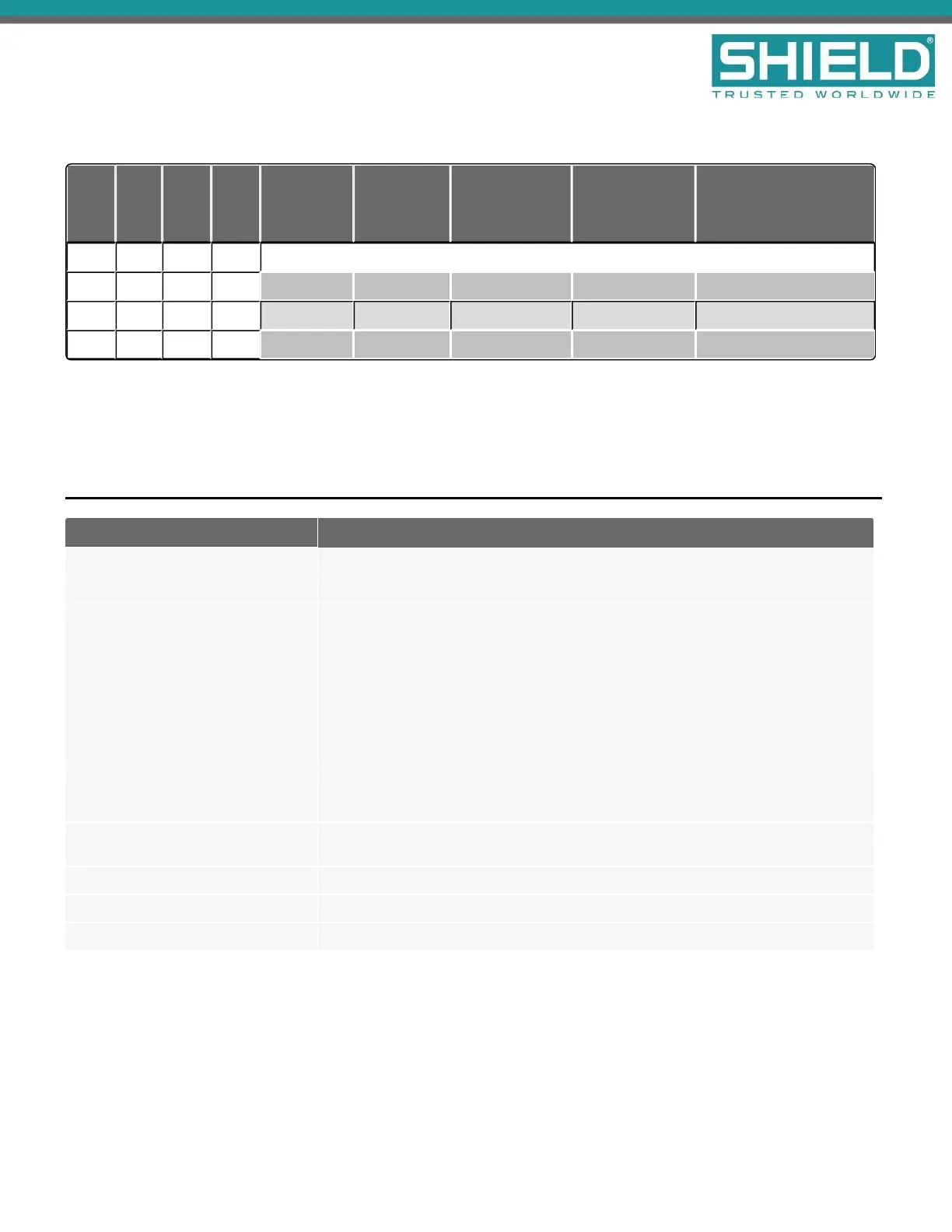
Special Application Mode Table
SW1 SW2 SW3 SW4
Battery
Mfr.
Battery
Size
Ground
Trouble
Detection
Impedance
Test
Intervals
Battery Missing
Trouble
ON ON ON ON RESERVED FOR FUTURE USE
ON ON OFF ON PowerSonic > 18Ah Static Disabled Reported
ON ON ON OFF Yuasa < 18 Ah Static 1 min Masked
ON ON OFF OFF Yuasa > 18Ah Static Disabled Reported
Light shading of the table indicates "production" or "demo" use.
Dark shading of the table indicates a "normal, but impedance test disabled" use.
Status Indicators
LED Indicator Condition
AC NORMAL The AC power is connected.
EARTH FLT The 24V DC supply is connected to the ground.
CHARGER FAULT w/ abnormal
HEARTBEAT
An internal fault has been detected in the power supply module. The HEARTBEAT
indicator blinks different patterns to indicate the fault.
1-1 AC Power is on and 24V output is not in regulation.
1-2 The battery voltage is too high.
1-3 The battery charge current is too high.
1-4 The battery charge current is low while the charger output current control is
MAXed.
BATTERY LOW (no CHARGER
FAULT)
The unit is operating from battery and the battery voltage is below 21 V OR The unit
is operating from AC power and the battery voltage is below 24 V.
BATTERY LOW and CHARGER
FAULT
The battery impedance exceeds the acceptable limit. Install new batteries.
BATTERY DISCON Standby batteries are disconnected.
HEARTBEAT The power supply is functioning.
DC OUT ON The 24V DC supply is supplying power to the load.
Power Supplies
SHIELD Fire, Safety & Security Ltd
Aura Fire Alarm Control Panel Installation Manual
Version 1.00 |June 2019 |MAN-1431VS
Page 93