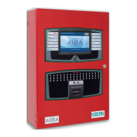
Installing Addressable Devices
This section describes installation requirements and constraints for addressable devices on the Aura Fire Alarm
ControlPanel. The addressable devices described in this section include SLC Devices.
SLC Detector Spacing
Install SLCdetectors with spacing as specified in NFPA 72.
SLC Device Detector Sensitivity
SLC device sensitivity is configurable using the panel GUI or LE2. Refer to the Programming the Panel for LE2
information. Sensitivity levels should be determined and planned in advance.
Detector Calibration / Drift Compensation
Detector calibration automatically occurs once per day. The Aura Fire Alarm ControlPanel is responsible for drift
compensation of individual smoke sensors. It will make automatic sensitivity checks and sensor adjustments
once per day.
Addressing an SLCModule
Shield Protocol
All SLCmodules must have a unique address number that acts as a point of reference for the panel. An
SLCmodule address number can be any number from 1-126. SLC sounder base addressing methods differ
depending on the model of the base. Refer to the installation instructions supplied with the specific sounder base
for details.
Detectors are addressed using a "smart card" installed in the detector base. All other devices are addressed by
setting DIP switches on the device. Refer to the installation instructions included with the specific device for
complete details.
Installation
SHIELD Fire, Safety & Security Ltd
Aura Fire Alarm Control Panel Installation Manual
Version 1.00 |June 2019 |MAN-1431VS
Page 43