Input and Output Functions Description
Trouble Routing Input Supervised input, requires 3.3K Ohm EOL resistor
Prog Routing Output
Volt-free output measures 3.3K Ohms in standby, switches to 680Ohms when
activated
Prog Routing Input 1 Supervised input, requires 3.3K Ohm EOL resistor
Prog Routing Input 2 Supervised input, requires 3.3K Ohm EOL resistor
Fire Relay Volt-free contact rated at 30V DC, 1A, Resistive
Trouble Relay Volt-free contact rated at 30V DC, 1A, Resistive
Superv Relay Volt-free contact rated at 30V DC, 1A, Resistive
Programmable Relay 1 Volt-free contact rated at 30V DC, 1A, Resistive
Programmable Relay 2 Volt-free contact rated at 30V DC, 1A, Resistive
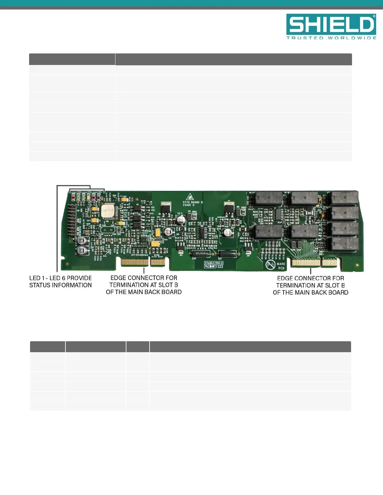
The System B Panel Module fits into slot B of the Main Back Board and controls the fire, trouble, and
programmable relays, auxiliary 24 volt, fire routing, trouble routing, and programmable inputs and outputs. This
figure illustrates System B Panel Module of the Aura Fire Alarm ControlPanel.
LED Label Name Color Description
LED 1 Heartbeat Red Identifies functional status of System B Panel Module.
LED 2 Rx Comms Green A blinking green light indicates that the module is receiving data.
LED 3 Tx Comms Green A blinking green light indicates that the module is transmitting data.
LED 4 Trouble Yellow A blinking yellow light indicates that an error condition.
LED 5 Input Active LED Red Indicates that an input is active.
LED 6 Output Active LED Red Indicates that an output is active.
Overview
SHIELD Fire, Safety & Security Ltd
Aura Fire Alarm Control Panel Installation Manual
Version 1.00 |June 2019 |MAN-1431VS
Page 55