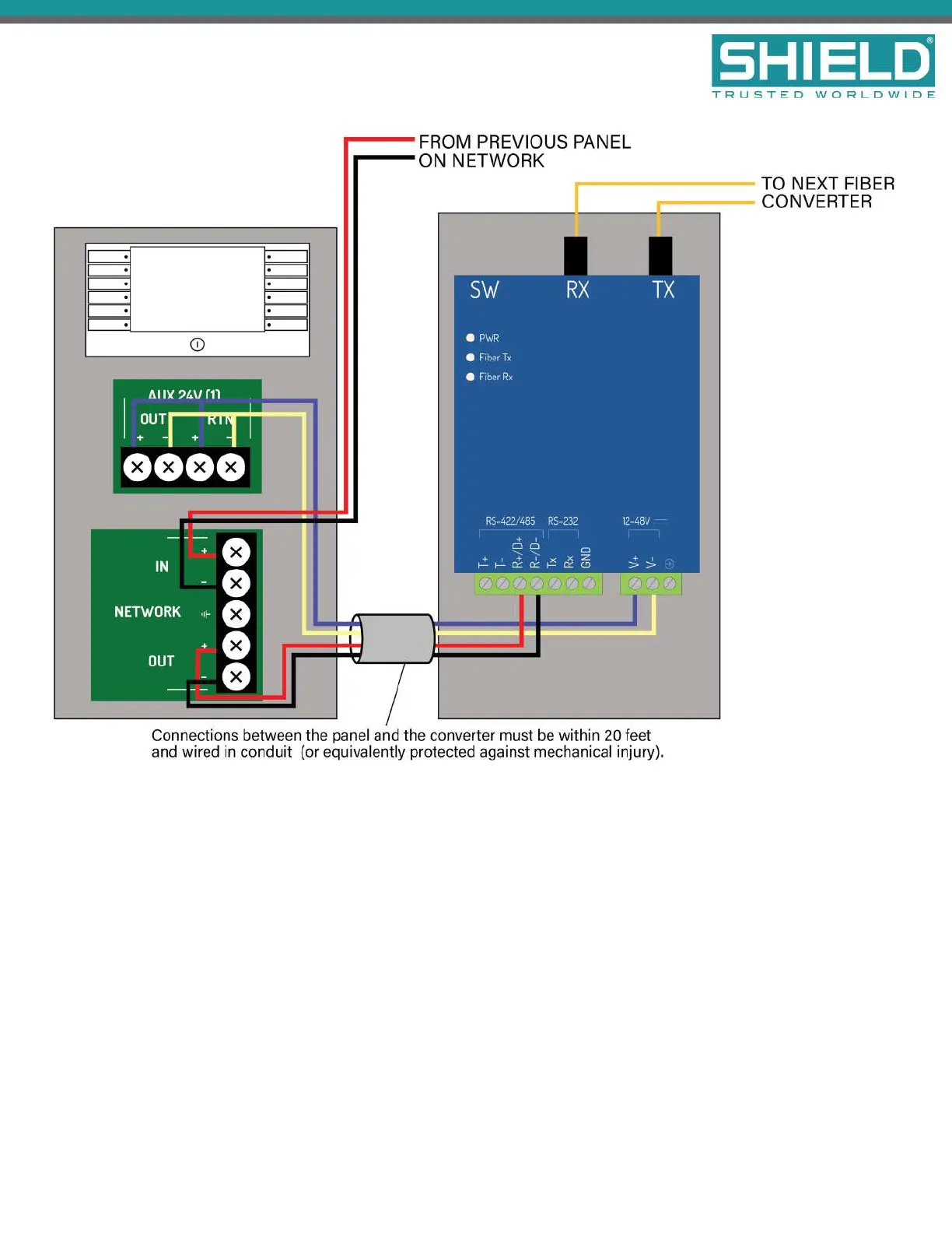
Detailed Fiber Converter Wiring Diagram
Do not insert more than one conductor per terminal. Use wire nuts or other suitable splice connectors to
connect the 24V DCcables to both the AUX 24V OUT and RTN terminals.
Installation
SHIELD Fire, Safety & Security Ltd
Aura Fire Alarm Control Panel Installation Manual
Version 1.00 |June 2019 |MAN-1431VS
Page 31