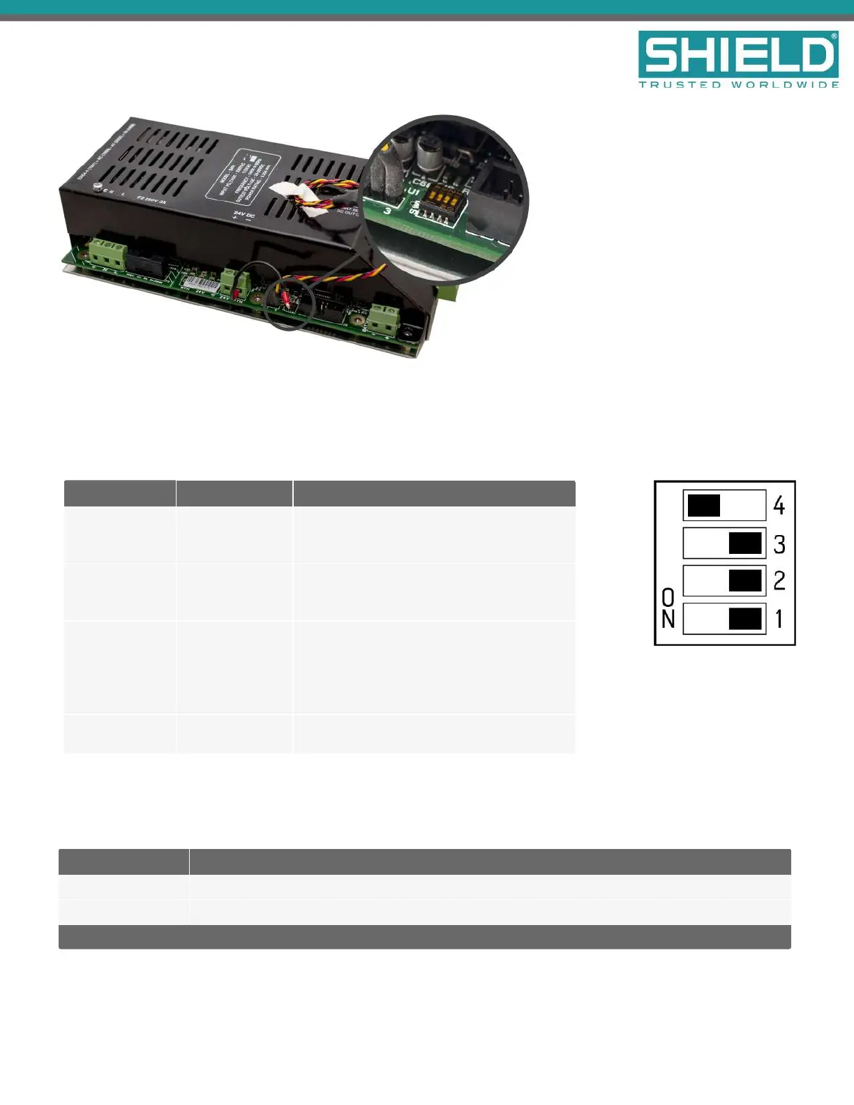
The tables below describe DIP switch settings 1 through 4 of the 5.25 Amp Power Supply. For ULcompliance,
DIPswitches should be set to the defaults, as shown.
SW1&2 together define the Battery Load Test (also known as Battery Impedance Test)
Switch 1 Switch 2 Description
Off (DEFAULT) Off (DEFAULT)
Recommended for standard operation. Load
test the battery every 59 minutes. Measured
voltage drop > 900mV fails the test.
Off On
NOTUSED. Load test the battery every 59
minutes. Measured voltage drop > 1100mV
fails the test.
On Off
Disable trouble reporting of disconnected
standby batteries. Load test the battery every
minute. Measured voltage drop > 900mV fails
the test. This setting also masks BATTERY_
MISSING troubles.
On On
Disable trouble reporting of standby battery
impedance. No load test performed.
Switch setting 3 is not used on the 5.25 Amp Power Supply and should be set to OFF.
SW4 defines Battery Manufacturer.
Switch 4 Description
On (DEFAULT) Sets standby batteries for the Powersonic manufacturer.
Off Sets standby batteries for the Yuasa manufacturer.
Other manufacturer batteries can be used. Consult the manufacturer's datasheet for proper settings.
Power Supplies
SHIELD Fire, Safety & Security Ltd
Aura Fire Alarm Control Panel Installation Manual
Version 1.00 |June 2019 |MAN-1431VS
Page 91