111
8009389/YN39/V3-0/2015-08| SICK OPERATING INSTRUCTIONS|GM35
Subject to change without notice
MAINTENANCE
9.5.3 Checking and adjusting the optical alignment of GM35
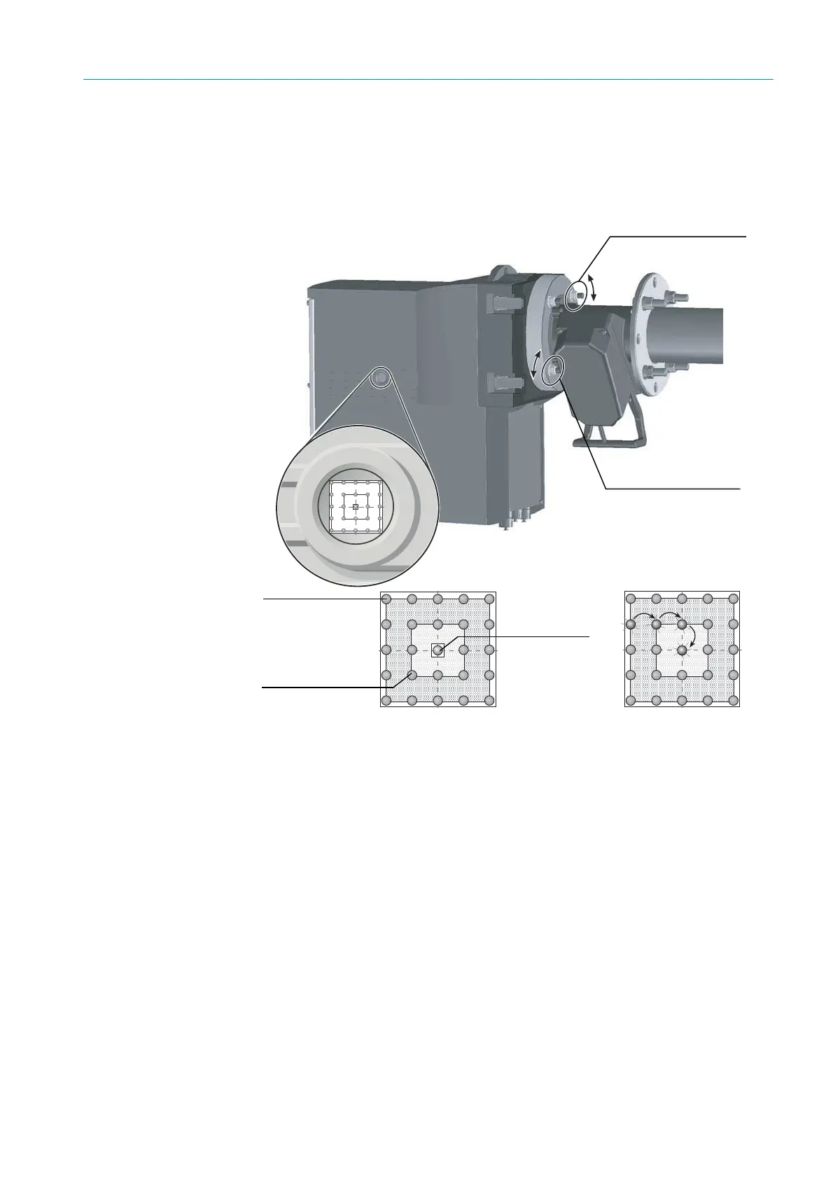
Check the alignment of the optical axis using the visor on the right-hand side of the SR-unit
enclosure and by making adjustments on the probe fixing on the device flange. The function
“ADJ. OPT. ALIGN” must be activated on systems with automatic alignment,
see “Aligning
the optical axis of the measuring probe”, page 84
.
Fig. 64: Aligning the optical axis
Visor The visor indicates the alignment of the optical axis between the SR-unit and the reflector
in the probe using a 5 x 5 LED matrix. The LEDs light up to represent the position of the light
beam on the reflector at the probe end. The cross hairs show three fields for aligning the
probe.
1 Adjust the optical alignment as shown on
page 111 by adjusting two screws on the
device flange with a 19 mm wrench whilst observing the light position of the LED at the
same time.
2 Horizontal probe adjustment causes the light spot to shift horizontally on the visor and
vertical adjustment causes a vertical shift.
3 Alignment is correct when the lit LED is located within the valid field within the cross
hairs, or is completely within the inner ring marking of the cross hairs.
Note For further information and significance of the LED matrix display on the GM35, see “Check-
ing the EvU display”, page 86
.
Probe adjustment,
horizontal
Probe adjustment,
vertical
Outside the valid
field
Optimum
alignment
Valid field