39
8009389/YN39/V3-0/2015-08| SICK OPERATING INSTRUCTIONS|GM35
Subject to change without notice
INSTALLATION
4.3 Installing the evaluation unit
The fitting location for the evaluation unit was defined during project planning (see “Project
Planning Checklist”, page 23) and prepared during onsite preinstallation as required.
▸ Make sure the CAN bus connection to the SR-unit selected during project planning is
usable at the planned installation location. The CAN bus connection cable delivered as
standard is 4 m long and serves to connect the evaluation unit directly at the measuring
point.
▸ Ensure easy access without problems. In particular, make sure the swivel door of the
evaluation unit can be opened without hindrance after fitting.
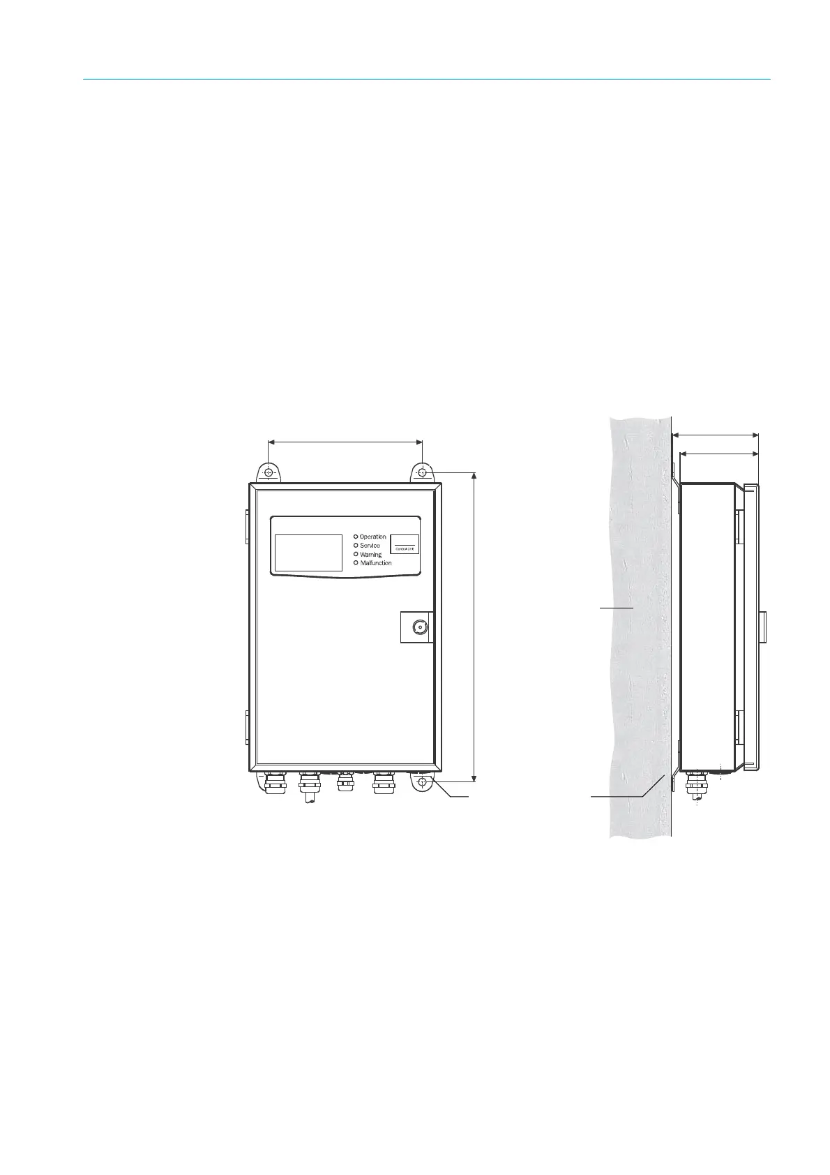
4.3.1 Installing the evaluation unit – sheet metal enclosure version
▸ Make ∅7.2 mm (for M8) mounting holes at the installation location according to the
Drilling plan.
▸ Attach the evaluation unit at the installation location using the 4 planned fastening
brackets with suitable screws.
Fig. 14: Installing the evaluation unit (sheet metal enclosure version)
4 mounting holes
∅ 8mm
Mounting surface
Fastening brackets