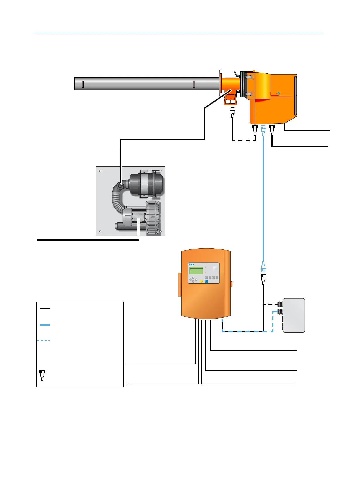
Fig. 11: Cable routing diagram
Power supply
(230/115 V AC) *
4m, 3 x 1.5mm
2
SR-unit
Measuring probe (example: GMP)
CAN *
1m
Evaluation unit
CAN bus extension, ready
for connection, 15 m
CAN bus cable (stan-
dard), 4 m *
Terminal box (option)
Standard cable
connection
Cable connection,
option
Cable in scope of
delivery
*
Prefabricated with plug-in
connector(s)
Purge air unit SLV4
(Standard for GMP
measuring probe)
Power supply 4 x
1.5 mm
2
Signal cable for:
• Filter monitoring of the SLV 4 – 2 x 0.6 mm
2
,
on pressure controller with flat pin bushings
6.3 x 0.8 mm (DIN 46247)
• Pressure connection
Functional
earth 2.5 mm
2
Power supply (230/115 V AC)
3 x 0.75 mm
2
3 binary inputs 6 x 0.5 mm
2
3 analog inputs 6 x 0.5 mm
2
3 binary outputs 6 x 0.5 mm
2
3 analog outputs 6 x 0.5 mm
2
to lengthen the CAN bus
connection with a cable
(1 x 2x 0.5mm
2
, twisted
pair, shielded) provided by
the customer
Cable connection for
optional terminal box