Home
SICK
Measuring Instruments
GM35
SICK GM35 User Manual
4
of 1
of 1 rating
148 pages
Give review
Manual
Specs
To Next Page
To Next Page
To Previous Page
To Previous Page
Loading...
60
8009389/YN3
9/V3-0/2015-08| SIC
K
OPERATING INSTRUCTIONS
|
G
M
3
5
Subject to change without notice
CONNECTING THE SYSTEM CONTROL UNIT - SCU
6.1.6
Menu overview (menu tree)
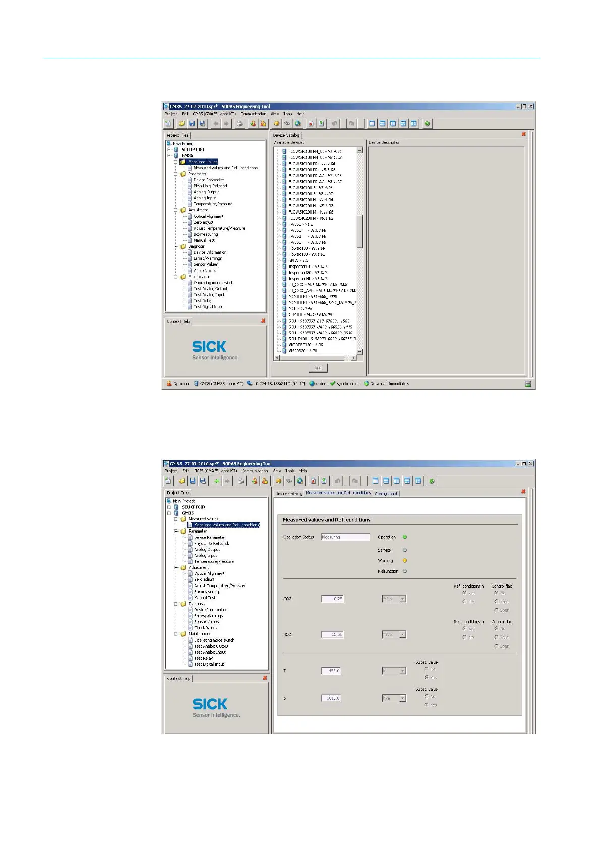
Fig.
27: GM3
5 menu tree
6.1.7
Measured values
Menu GM35/Measured values
Fig.
28: Menu: Measured values and Re
f. conditions
59
61
Table of Contents
Default Chapter
3
Table of Contents
3
1 Safety Information
9
Permissible Users
9
Correct Handling
9
Safety
9
Behavior During Purge Air Failure
10
2 Product Overview
11
Use and Proper Application
11
Conformities and Certifications
11
Overview of Standard Components
12
Measuring Probe in Detail
14
GMP - Probe with Open Measuring Gap and Vertical Purge Air Outlet
14
GM35 Options and Accessories
18
Functional Principle
19
Opto-Electronic In-Situ Measuring Principle
19
Signal Evaluation
20
Automatic Check Cycles
21
3 Project Planning Information
22
Work Steps from System Selection to Start-Up
22
Project Planning Checklist
23
Initial Onsite Installation
26
Assembly Preparation at the Measuring Point
26
Uncovering the Duct
27
Installing the Flange with Tube
27
Installation Steps: Fitting the Flange with Tube
28
Installation Preparation for the Purge Air Unit
29
Duct Insulation
29
Installation Preparation for the Evaluation Unit
30
Preparations for Electrical Installation
30
Electrical Protection
30
Specifications on Electric Isolation of the Evu
30
Electrical Installation Safety Information
30
Electrical Protection
32
Specifications on Electric Isolation of the Evu
32
Laying Connection Lines
33
CAN Bus Wiring
34
4 Installation
36
Preparations
36
Checking the Scope of Delivery
36
Installation Prerequisites
36
Fitting System Components
37
Information on the SR-Unit and Measuring Probe
37
Installing the Purge Air Unit
37
Terminal Box (Option)
38
Installing the Evaluation Unit
39
Installing the Evaluation Unit - Sheet Metal Enclosure Version
39
Installing the Evaluation Unit - Cast Enclosure Version
40
Electrical Connection of System Components
41
Electrical Connection for the Purge Air Unit
41
CAN Bus Wiring Options
42
Electrical Connection of the Evaluation Unit
44
5 Handling the Evaluation Unit
47
User Qualifications
47
Operating Elements
47
Function Buttons and Menu Overview
48
Display Contents
49
Menu Structure
49
Menu Structure Measuring Mode
49
Menu Structure Diagnosis
50
Menu Structure Calibration
50
Menu Structure Configuration
51
Menu Structure Maintenance Mode (Maint)
52
6 Connecting the System Control Unit - SCU
53
SCU Connection to the GM35
53
Electrical Connection of the SCU to the GM35
53
Configuring and Operating Using SOPAS
53
Connecting the GM35 Evaluation Unit Via the SCU Operating Unit
55
Direct Serial Connection to the GM35 Evaluation Unit
57
Changing the User Level
59
Menu Overview (Menu Tree)
60
Measured Values
60
Menu Parameter
61
Menu Adjustment
66
Menu Diagnosis
70
Menu Maintenance
72
7 Start-Up
75
Preparations
75
Required Qualifications and Further Prerequisites
75
Start-Up Procedure Overview
75
General Preparation
75
Required Tools and Materials for the Installation
76
Mechanical Preparations for the SR-Unit and Reflector
77
Checking the Scope of Delivery
77
Transport Safety Devices
77
Cleaning the Optical Interface
78
Aligning the Measuring Probe in Flow Direction
79
Installing the SR-Unit on the Measuring Probe
80
Adjustment Work
82
Prerequisites and Location Selection for Adjustment Work
82
Adjustment Preparations
83
Aligning the Optical Axis of the Measuring Probe
84
Performing Zero Adjust
87
Starting Measuring Operation
88
Starting up the Purge Air Supply
88
GPP Measuring Probes: Power Supply
89
Installing the GM35 SR-Unit and Measuring Probe on the Duct.89
89
Electrical Connections and Checking the Optical Alignment
90
Weatherproof Cover
92
Evaluation Unit Start-Up
93
Setting up the SCU System Control Unit
93
Mapping Table
93
Measured Values on SCU - Measured Value (MV)
93
Control Values on SCU - Monitor Values (MO)
93
Operating State of the GM35 - State (S)
94
8 Test Gas Measurement with GPP Measuring Probes
96
One-Off Preliminary Measurement/Determining the Settings
97
Manual Gas Test
98
9 Maintenance
99
Safety
99
Preparation and General Preparatory Work
101
Maintenance Work on SR-Unit and Measuring Probe
103
Taking the SR-Unit with Measuring Probe off the Sample Gas Duct
103
Visual Inspection and Enclosure Cleaning
104
Cleaning the Optical Interfaces on the SR-Unit
104
Maintenance Work on the Purge Air Supply
106
Safety
106
General Information on Maintenance Work on the Purge Air Supply
106
Preparation and General Inspection
106
Checking and Replacing the Purge Air Filter
107
Restarting and Checking the Purge Air Unit
109
Resuming Measuring Mode
109
Inserting in the Sample Gas Duct
109
Electrical Connection
110
Checking and Adjusting the Optical Alignment of GM35
111
Completing Maintenance Work at the Measuring Point
112
Evaluation Unit (Evu)
112
Box Measuring: Checking the Measuring Ducts for CO or N 2 O
113
And CO 2
113
Determining the Necessary Test Gas Concentration
113
Carrying out Measurement
113
Restart Measuring Mode
115
Box Measuring: Checking the Measuring Ducts for H O and CO
116
Setpoint Values
116
Carrying out Measurement
116
Restart Measuring Mode
118
10 Troubleshooting and Clearing Malfunctions
119
Malfunction Categories/Possible Effects
119
Purge Air Failure
119
Integrated Monitoring and Diagnosis System
120
Troubleshooting and Clearing Malfunctions, Evaluation Unit
121
Error Messages for the GM35 SR-Unit
121
Error Messages for the Measuring Probe
124
Warning Messages for the GM35 SR-Unit
124
Warning Messages for the Measuring Probes
126
Further Tips on Troubleshooting
126
11 Technical Data, Consumables and Spare Parts
128
Data Tables
128
Measuring Components and Accuracy
128
Stability
129
GM35-System Components
130
Dimension Drawings
132
GM35 SR-Unit Dimensions
132
Open Measuring Probe - GMP, Dimensions
133
GPP Measuring Probes Dimensions
134
Dimension Drawing of GM35 Evaluation Unit, Sheet Metal Enclosure
135
Dimension Drawing for GM35 Evaluation Unit, Cast Enclosure
136
Purge Air Unit Dimension Drawing
137
Weatherproof Covers Dimension Drawings
137
Terminal Box for CAN Bus Connection, Dimension Drawing
139
Flange with Tube, Dimension Drawing and Version Table
139
Consumables and Spare Parts
140
Consumable Parts for 2-Years Operation
140
Spare Parts for the Sender/Receiver Unit
140
Probe Spare Parts
143
Spare Parts for the Evaluation Unit
144
Spare Parts for Purge Air Unit
145
Spare Parts, Miscellaneous
145
Fixing Accessories
145
Fixing Accessories, Measuring Probe - Flange
145
Fixing Accessories, SR-Unit - Measuring Probe
145
Other manuals for SICK GM35
Installation Operation & Maintenance
130 pages
4
Based on 1 rating
Ask a question
Give review
Questions and Answers:
Need help?
Do you have a question about the SICK GM35 and is the answer not in the manual?
Ask a question
SICK GM35 Specifications
General
Brand
SICK
Model
GM35
Category
Measuring Instruments
Language
English
Related product manuals
SICK GM32
80 pages
SICK MLG-2 Pro
138 pages
SICK DL100 Pro
126 pages
SICK LFP CUBIC
72 pages
SICK FLOWSIC550
52 pages
SICK FLOWSIC500
176 pages
SICK FLOWSIC100
184 pages
SICK MLG-2 Prime
62 pages
SICK DUSTHUNTER T
552 pages
SICK FLOWSIC600-XT
164 pages
SICK DUSTHUNTER T100
261 pages
SICK FLOWSIC100 Flare
266 pages