89
8009389/YN39/V3-0/2015-08| SICK OPERATING INSTRUCTIONS|GM35
Subject to change without notice
START-UP
3 Connect the purge air hose from the purge air unit to the purge air connection of the
measuring probe using a hose clamp, or to the pressure controller when used (see
page 88).
4 Switch the purge air supply on.
Purge air supply is now activated and protects the measuring system against
contamination and overheating. Purge air supply must never be switched off while the
measuring probe is in the sample gas duct.
5 If not already done so, attach clearly visible warnings on all switch devices that can
switch off the purge air supply to prevent it from being deactivated inadvertently.
7.6.2 GPP measuring probes: Power supply
If a GPP measuring probe is used, the optical interfaces must be heated to the necessary
operating temperature before the measuring probe is inserted in the duct:
1 Connect the GPP measuring probe to the power supply.
If the power supply cable of the measuring probe to be used for continuous measuring
operation cannot be connected until the measuring probe is inserted in the duct, or if it
cannot be switched on, use a temporary power supply cable similar to the one that may
have been used for the zero adjust (
page 87).
2 Wait until the operating temperature of the optical interfaces in the measuring probe
has been reached.
3 Leave the power supply connected while inserting the measuring probe in the duct (
see
page 89) and while it is inside the duct.
7.6.3 Installing the GM35 SR-unit and measuring probe on the duct
▸ If present, remove the cover on the duct-side flange with tube.
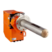
▸ Insert the measuring probe with mounted SR-unit in the duct-side flange with tube. When
using a GMP measuring probe, the purge air supply must remain connected to the
measuring probe and in constant operation. The power supply to GPP measuring probes
for heating the optical interfaces must not be interrupted.
▸ Fit the measuring probe to the duct-side flange using the set of fixing parts delivered as
described on page 90. The set of fixing parts comprises 4 M16x60 screws, each with
nut and 2 washers.
WARNING: Protection against hazards through hot resp. aggressive gases
▸ Wear suitable protective clothing (mask, gloves, working clothing and other)
to avoid health risks and other hazards when opening the sample gas duct.
If the protective clothing does not allow safe working on the open sample
gas duct under the current conditions or if the sample gas duct is in
operation and cannot be opened as this would allow gas to escape or air to
enter the duct:
Contact the persons responsible to have the sample gas duct shut down for
the duration of the installation procedure and, when possible, have the duct
flushed with ambient air to ensure safe installation.

 Loading...