29
8009389/YN39/V3-0/2015-08| SICK OPERATING INSTRUCTIONS|GM35
Subject to change without notice
PROJECT PLANNING INFORMATION
3.3.4 Installation preparation for the purge air unit
Is a purge air unit to
be used?
This step is only relevant for device configurations containing a purge air unit. GM35
configurations with GPP measuring probes do not require purge air.
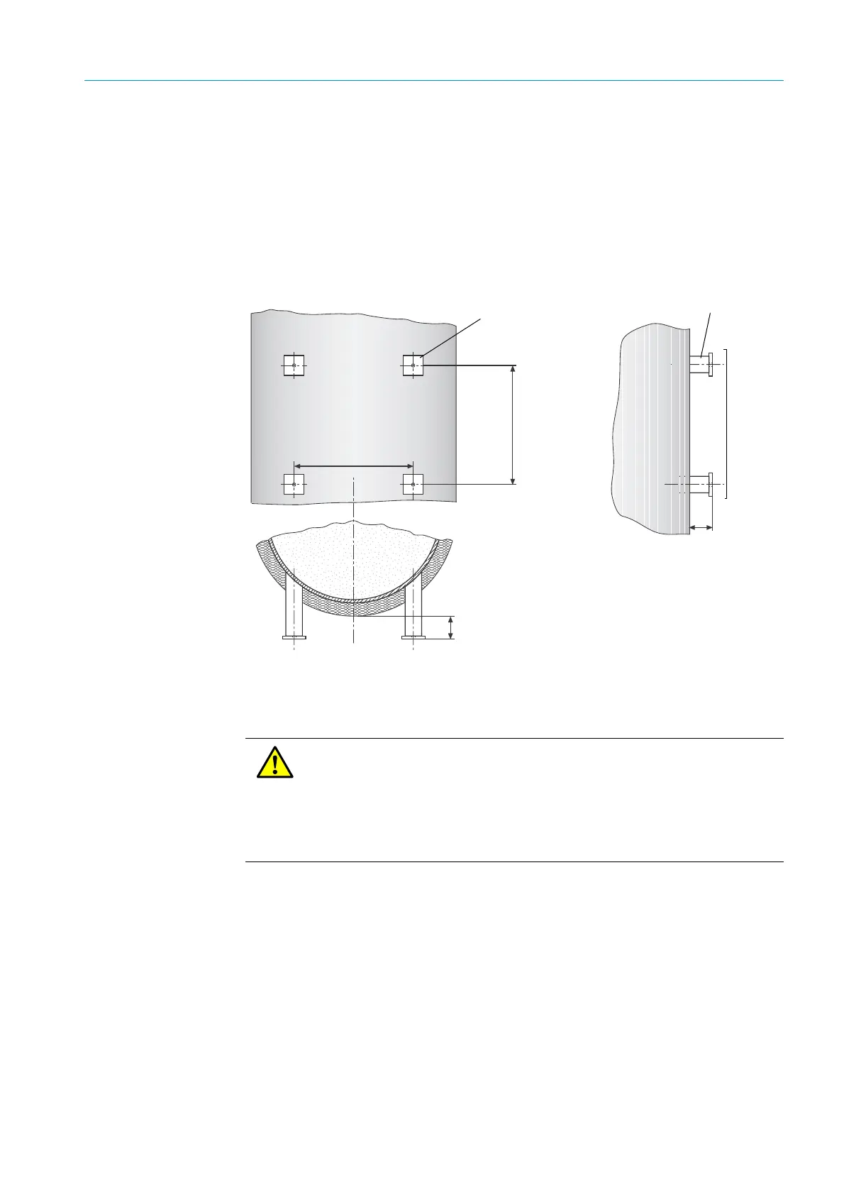
1 Make brackets from steel pipes (e.g. 50 x 5) with flanges (e.g. FL 60 x 8 x 60) for the
four fixing points of the purge air unit ; bore M10 threads in the mounting holes.
2 Weld the brackets on as shown when using steel ducts.
For stone stacks, fit retainer plates to each steel pipe or use a different, suitable mounting
for the purge air unit.
3
Fitting recommendation for purge air units (duct diameter not representative)
3.3.5 Duct insulation
▸ Refit the thermal duct insulation; reinforce the insulation when necessary.
Steel pipe 50 x 5
DIN 2391
Purge air unit fastening
50 mm protrusion for circular duct cross-section
Flange 60 x 8 60
DIN 174
CAUTION: Device failure due to high ambient temperatures
The SR-unit of the GM35 is designed for a maximum ambient temperature of
+55 °C. Radiant heat on the enclosure surface can, under certain
circumstances, lead to temperatures higher than the measured air
temperature.
▸ Therefore, design insulation and radiation shielding so that temperature
limits are reliably maintained.